
A laser pipe cutting machine

A tube cutting machine and laser technology, which is applied to laser welding equipment, tubular objects, welding/cutting auxiliary equipment, etc., can solve the problems affecting processing accuracy, support, and general clamping effect, and achieve the effect of good synchronization

Active Publication Date: 2021-06-11
佛山汇百盛激光科技有限公司
View PDF10 Cites 0 Cited by
  • Summary
  • Abstract
  • Description
  • Claims
  • Application Information

AI Technical Summary

Problems solved by technology

[0005] In view of the shortcomings of the above-mentioned prior art, the object of the present invention is to provide a laser pipe cutting machine, which aims to solve the problem that the existing pipe cutting machine has a general support and clamping effect on pipe fittings and affects the processing accuracy.

Method used


Image

  • A laser pipe cutting machine
  • A laser pipe cutting machine
  • A laser pipe cutting machine

Examples


Embodiment Construction

[0032] The present invention provides a laser pipe cutting machine. In order to make the purpose, technical solution and effect of the present invention clearer and clearer, the present invention will be further described in detail below with reference to the accompanying drawings and examples. It should be understood that the specific embodiments described here are only used to explain the present invention, and are not intended to limit the protection scope of the present invention.

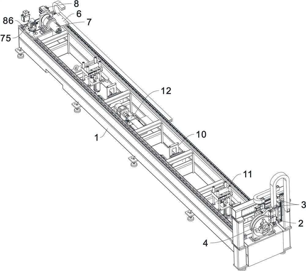
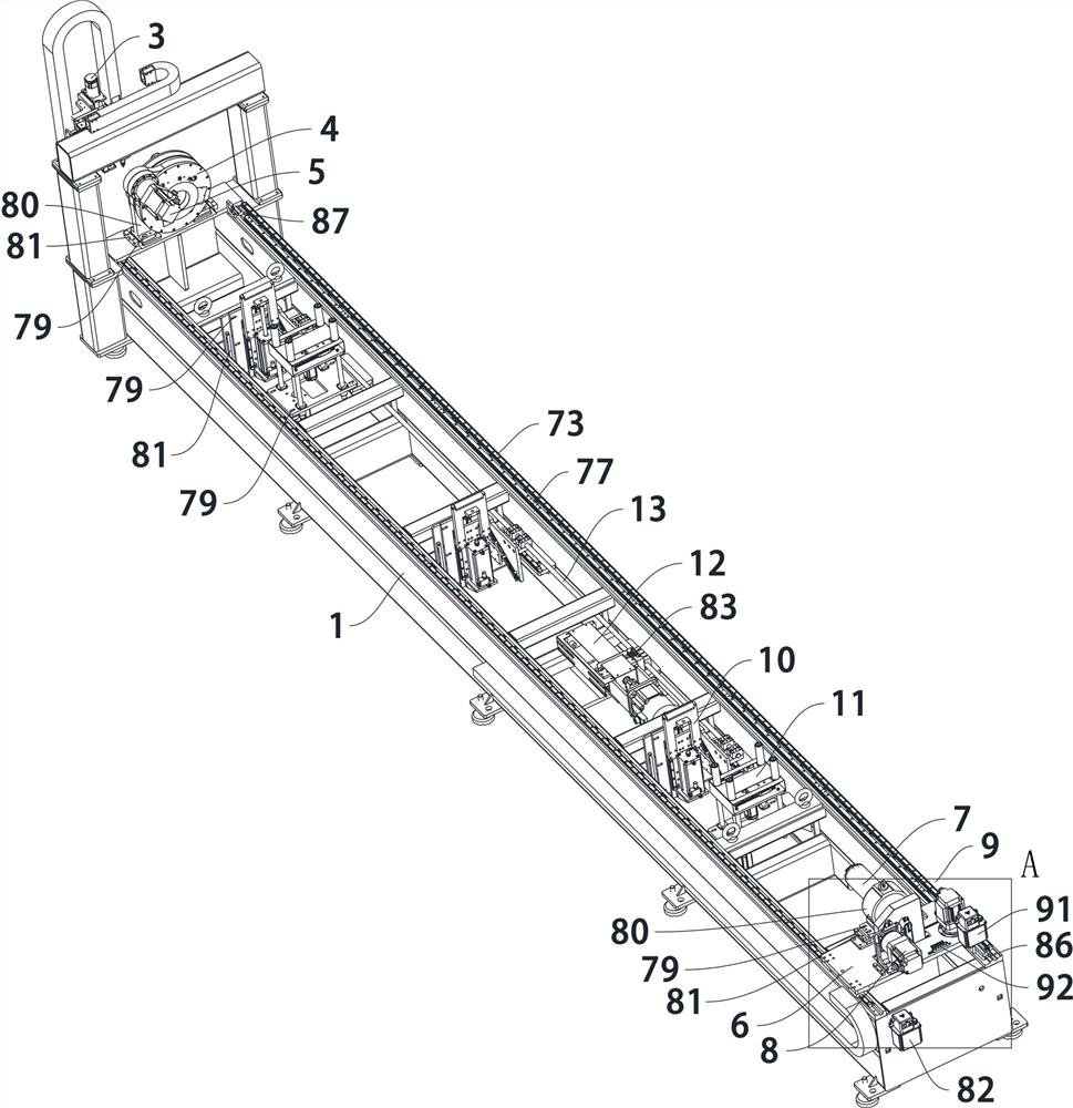
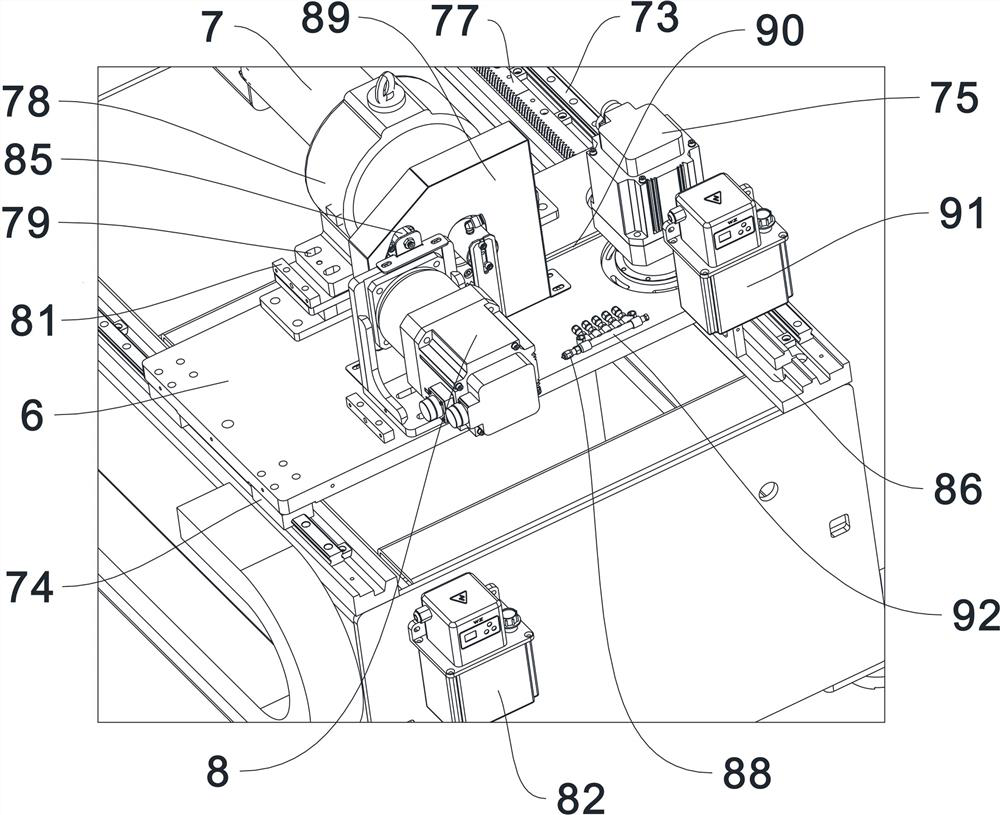
[0033] see Figure 1-12 , The present invention provides a laser pipe cutting machine, comprising: a bed 1, a laser head 2, a first motor 3, a front chuck 4, a second motor 5, a workbench 6, a rear chuck 7, a third motor 8, Moving mechanism 9, follow-up support mechanism 10, clamping mechanism 11 and slide mechanism 12; said laser head 2 and front chuck 4 are arranged on the front end of said bed 1 respectively, and said first motor 3 is used to drive The laser head 2 moves along the X-axis an...


PUM


Abstract

The invention discloses a laser pipe cutting machine, which comprises a bed, a laser head, a first motor, a front chuck, a second motor, a workbench, a rear chuck, a third motor, a moving mechanism, a follow-up support mechanism, a pair of Clamp mechanism and sliding table mechanism; the first motor is used to drive the laser head to move along the X-axis and Z-axis above the bed; the second motor is used to drive the front chuck to clamp the pipe; the The third motor is used to drive the rear end of the rear chuck to clamp the pipe; the moving mechanism is used to drive the workbench and the rear chuck to slide on the bed; the follow-up support mechanism is used to Support pipe fittings; the clamping mechanism is used to clamp pipe fittings; the sliding table mechanism is used to drive the follow-up support mechanism to rise or fall in the bed; by setting the above settings, the laser cutting pipe can be lifted as a whole The clamping and positioning effect of the machine to the pipe fittings is improved, and the synchronization between the various mechanisms is better at the same time.

Description

technical field [0001] The invention relates to the technical field of laser cutting equipment, in particular to a laser pipe cutting machine. Background technique [0002] Laser pipe cutting machine is mainly used for cutting pipes such as round pipes and square pipes. It has the characteristics of high precision, fast cutting, not limited to cutting pattern restrictions, and smooth incision, so it gradually replaces traditional metal cutting equipment. [0003] For pipe fittings with small pipe diameters, they will shake during the rotation process and cause shaking. Usually, a pipe fitting clamping mechanism is installed on the bed to prevent the pipe fittings from shaking. The effect is average, but it will still affect the machining accuracy of the cutting head. [0004] It can be seen that the prior art still needs to be improved and enhanced. Contents of the invention [0005] In view of the deficiencies of the above-mentioned prior art, the object of the present ...

Claims


Application Information

Patent Timeline
Patent Type & Authority Patents(China)
IPC IPC(8): B23K26/38B23K26/70B23K37/053B23K101/06
CPCB23K26/38B23K37/0533B23K26/702B23K2101/06
Inventor 梁建冬黄思薪严君仪杨红杰练振达廖谷祥左建林罗勇杰杨广朝林哲肖冲黄海涛王红胜吴昌坚
Owner 佛山汇百盛激光科技有限公司
Learn More