Electronic throttling device for refrigeration system
A technology of throttling device and refrigeration system, applied in valve device, valve operation/release device, valve details, etc., can solve the problems of control signal out-of-step, reducing the service life of stepper motor, unable to meet the requirements of use, etc. Accurate position feedback, high reliability and compact structure
- Summary
- Abstract
- Description
- Claims
- Application Information
AI Technical Summary
Problems solved by technology
Method used
Image

Examples
Embodiment 1
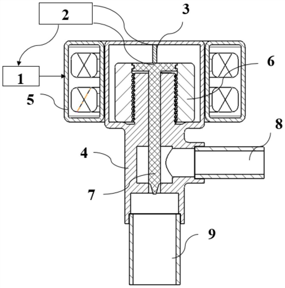
[0016] like figure 1 As shown, an electronic throttling device for a refrigeration system according to Embodiment 1 includes: a controller 1, a signal transmitter 2, a metal wire 3 as a position sensor, a valve body 4, a coil 5, a rotor 6, The valve stem 7, the inlet pipe 8 and the outlet pipe 9, wherein: the valve stem 7 is arranged in the valve body 4, the rotor 6 is arranged on the valve body 4, the coil 5 is covered outside the valve body 4, and one end of the wire 3 is connected to the valve body 4 The upper end is connected, the other end is arranged on the top of the valve stem 7, the outlet pipe 9 is arranged at the bottom of the valve body 4 and is connected with the valve stem 7, the inlet pipe 8 is arranged on the side of the valve body 4, the controller 1 is connected with the coil 5, and the signal transmitter 2 is connected to controller 1 and wire 3.
[0017] The metal wire 3 is made of alloy.
[0018] When the valve stem 7 is linearly displaced, the wire 3 is...
Embodiment 2
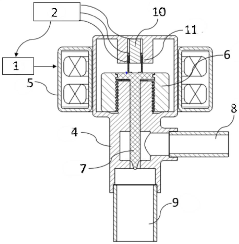
[0021] like figure 2 As shown, the main structure of the electronic throttling device for a refrigeration system involved in the second embodiment is the same as that of the first embodiment, except that the position sensor in this embodiment is a sliding potentiometer 10, and one end of the sliding potentiometer 10 is fixed Set on the upper end of the valve body 4, the contact slide 11 at the other end of the sliding potentiometer 10 is fixedly connected with the top of the valve stem 7, the linear displacement of the valve stem 7 drives the contact slide 11 to move, and the resistance of the contact slide 11 The total resistance value of the sliding potentiometer 10 is connected to the signal transmitter 2 through three contact wires.
[0022] The controller 1 controls the rotation of the rotor 6 by sending a pulse signal to the coil 5, and then converts the rotational motion of the rotor 6 into the linear displacement of the valve stem 7 through the threaded transmission p...
PUM
 Abstract
Description
Claims
Application Information
 - R&D
- Intellectual Property
- Life Sciences
- Materials
- Tech Scout
- Unparalleled Data Quality
- Higher Quality Content
- 60% Fewer Hallucinations
Browse by: Latest US Patents, China's latest patents, Technical Efficacy Thesaurus, Application Domain, Technology Topic, Popular Technical Reports.
© 2025 PatSnap. All rights reserved.Legal|Privacy policy|Modern Slavery Act Transparency Statement|Sitemap|About US| Contact US: help@patsnap.com