Pneumatic tire

A technology of pneumatic tires and tire shoulders, applied in tire parts, tire tread/tread pattern, vehicle parts, etc., can solve the problems of low block rigidity, tire heel and toe wear, etc., to alleviate the rigidity difference, improve the Drainage, the effect of suppressing the wear of the heel and toe

Active Publication Date: 2021-03-26
THE YOKOHAMA RUBBER CO LTD
View PDF10 Cites 0 Cited by
  • Summary
  • Abstract
  • Description
  • Claims
  • Application Information

AI Technical Summary

Problems solved by technology

However, in this configuration, the block rigidity is low, so there is a problem that heel and toe wear tends to occur.

Method used


Image

  • Pneumatic tire
  • Pneumatic tire
  • Pneumatic tire

Examples


Embodiment

[0146] Figure 12 It is a graph showing the results of the performance test of the pneumatic tire according to the embodiment of the present invention.

[0147] In this performance test, evaluations regarding (1) uneven wear resistance performance and (2) wet traction performance were performed for various test tires. In addition, a test tire having a tire size of 225 / 70R19.5 was assembled to a JATMA-specified rim, and a JATMA-specified internal pressure and a prescribed load were applied to the test tire. In addition, the test tires were attached to the front wheels of a 2-D (pickup truck) as a test vehicle.

[0148] In the evaluation of (1) uneven wear resistance performance, the test vehicle was driven on a paved road for 40,000 [km], and then the heel and toe wear generated on the block was observed and evaluated. This evaluation was performed by index evaluation using the conventional example as a reference (100), and the larger the numerical value, the better.

[0149...


PUM


Abstract

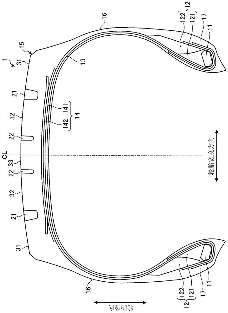
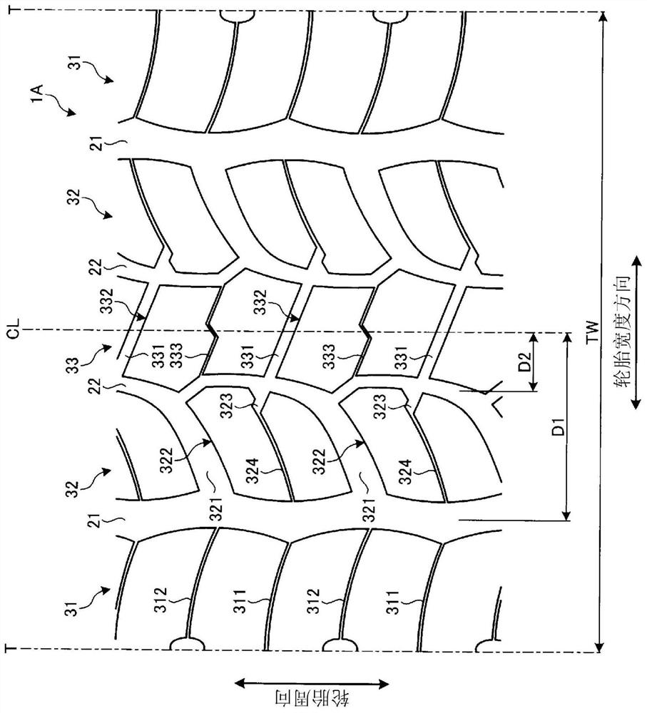
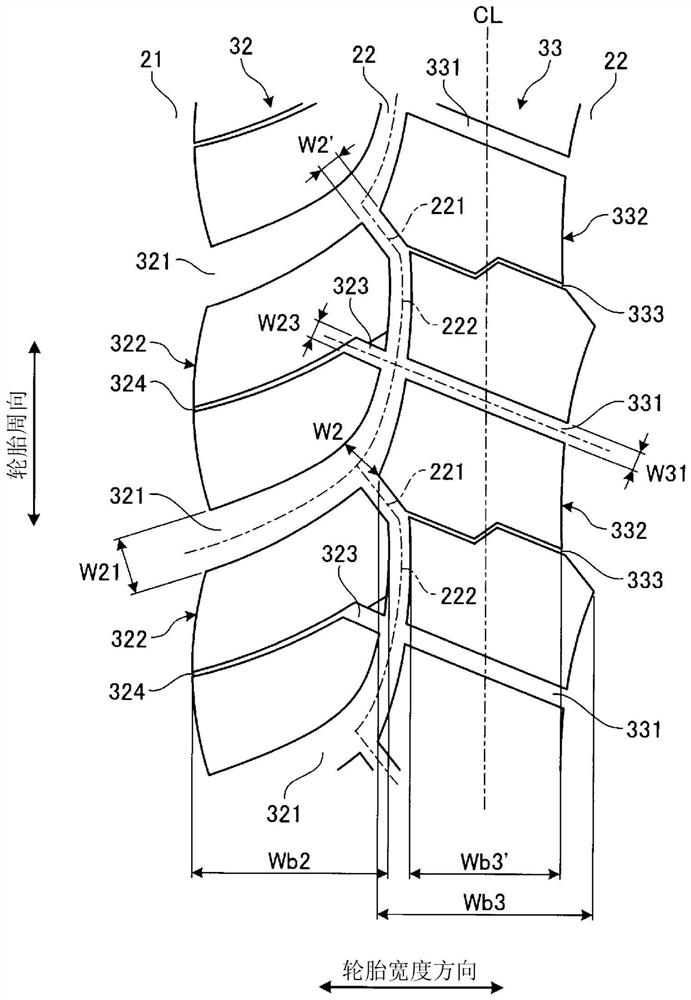
In this pneumatic tire 1A, a center land part 33 is provided with a plurality of center lug grooves 331 penetrating through the center land part 33, and a plurality of center blocks 332 demarcated bythe center lug grooves 331. A middle land part 32 is also provided with a plurality of middle lug grooves 321 penetrating through the middle land part 32, a plurality of middle blocks 322 demarcated by the middle lug grooves 321, notch parts 323 formed on extension lines of the center lug grooves 331 as edge parts on a center main groove 22 side of the middle blocks 322, and middle sipes 324 extending from the notch parts 323 and opening to the edge parts on a shoulder main groove 21 side of the middle blocks 322.

Description

technical field [0001] The present invention relates to a pneumatic tire, and more specifically, to a pneumatic tire capable of improving uneven wear resistance and wet traction performance of the tire. Background technique [0002] Pneumatic tires for pickup trucks have block rows defined by penetrating lug grooves in the central region of the tread portion in order to improve wet traction. However, in this configuration, the block rigidity is low, so there is a problem that heel and toe wear tends to occur. The technique described in Patent Document 1 is known as a conventional pneumatic tire that involves such a problem. [0003] prior art literature [0004] patent documents [0005] Patent Document 1: Japanese Patent Application Laid-Open No. 61-102301 Contents of the invention [0006] The problem to be solved by the invention [0007] An object of the present invention is to provide a pneumatic tire capable of improving uneven wear resistance and wet traction p...

Claims


Application Information

Patent Timeline
Patent Type & Authority Applications(China)
IPC IPC(8): B60C11/03B60C11/12B60C11/13
CPCB60C11/0306B60C11/11B60C2011/0346B60C2011/0381B60C2011/1209B60C2011/1213B60C11/1281B60C2011/0374B60C2011/0365B60C2011/0372B60C11/1384B60C11/1259B60C11/0309B60C11/1204B60C11/1236B60C2011/0348B60C2011/0355
Inventor 德永丽雅
Owner THE YOKOHAMA RUBBER CO LTD
Why Eureka
Try Eureka