
Method and system for slab length measurement using laser speed sensor

A laser speed measurement and sensor technology, which is applied to the device using optical methods, the configuration of optical devices, indicating equipment/measuring equipment, etc. Scale change and other problems, to achieve the effect of accurate casting length information, accurate tracking, and reduced maintenance costs

Active Publication Date: 2022-07-15
SHANGHAI BAOSIGHT SOFTWARE CO LTD
View PDF6 Cites 0 Cited by
  • Summary
  • Abstract
  • Description
  • Claims
  • Application Information

AI Technical Summary

Problems solved by technology

In this patent, there is a certain error when measuring the slab tracking. Under normal circumstances, the slab sizing error is within ±20mm. If the vibration of the roller table will cause the angle between the camera and the roller table to change, it will also cause the slab The size of the billet changes, and the small movement of the camera lens cannot be observed by the naked eye
In addition, since the surface of the slab is not smooth enough, it is easy to cause signal loss due to diffuse reflection

Method used


Image

  • Method and system for slab length measurement using laser speed sensor
  • Method and system for slab length measurement using laser speed sensor
  • Method and system for slab length measurement using laser speed sensor

Examples


Embodiment Construction

[0038] The present invention will be described in detail below with reference to specific embodiments. The following examples will help those skilled in the art to further understand the present invention, but do not limit the present invention in any form. It should be noted that, for those skilled in the art, several changes and improvements can be made without departing from the inventive concept. These all belong to the protection scope of the present invention.

[0039] The concrete of the present invention is implemented through the following steps:

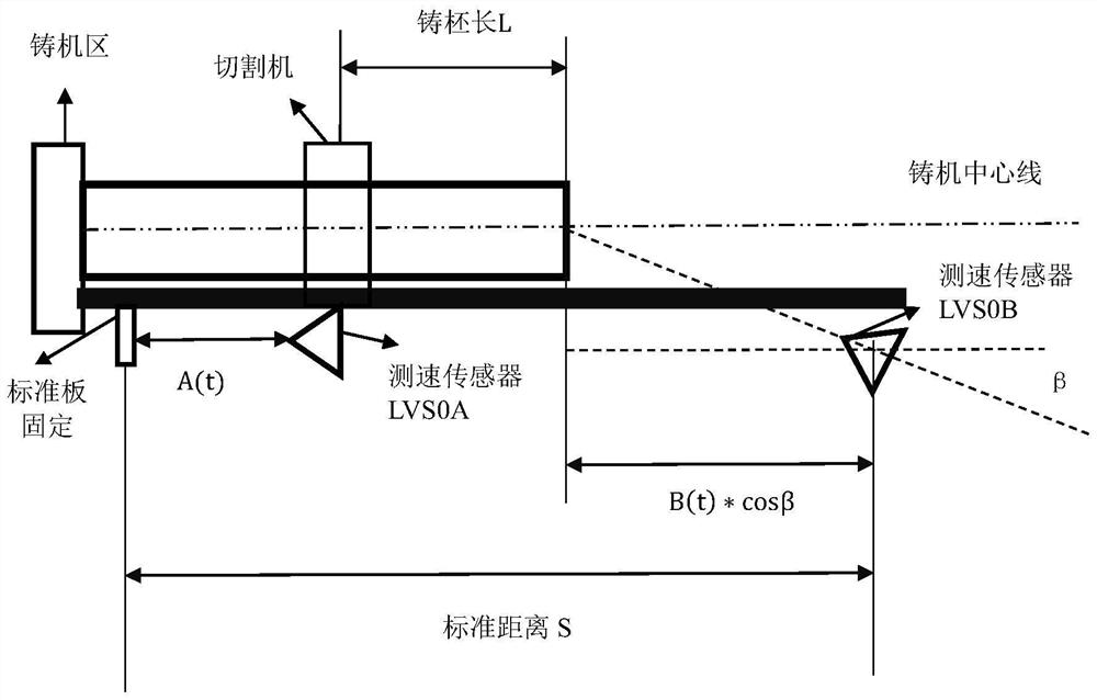
[0040] Laser speed measurement steps: add a laser speed measurement sensor before and after the cutting roller table, which is recorded as the front laser speed measurement sensor and the rear laser speed measurement sensor. When there is a slab in the middle of the cutting roller table, start the laser speed measurement sensor to measure the speed;

[0041] Steps of distance measurement: After the control unit recognizes...


PUM


Abstract

The invention provides a method and a system for tracking and measuring slabs by using a laser speed measuring sensor. A laser speed measuring sensor is added before and after the cutting roller table, which is recorded as the front laser speed measuring sensor and the rear laser speed measuring sensor. When the middle of the cutting roller table When there is a slab, start the laser speed measuring sensor to measure the speed; the control unit recognizes the valid signal of the laser speed measuring sensor, and integrates the speed value according to the valid signal to obtain the moving distance value. The control unit identifies the invalid signal of the laser speed measuring sensor, and uses The auxiliary encoder calculates the travel distance value based on the invalid signal. It can solve the problem of errors caused by the slippage of the length measuring roller, and infer whether there is a slippage problem according to the accuracy tracking information; the tracking of abnormal positions is more accurate, which can reduce the length loss of waste blanks, so that the length measuring roller can be cancelled and the maintenance of mechanical equipment is reduced. After the tracking accuracy is improved, the casting length information is more accurate, and the slab length information is also more accurate.

Description

technical field [0001] The invention relates to the technical field of slab length measurement, in particular to a method and a system for measuring slab length by using a laser speed measuring sensor, in particular to a method for measuring the length of a continuous casting slab based on a laser speed measuring sensor . Background technique [0002] The position information of the dummy bar head, tail, slab head and slab tail, as well as length information such as casting length and slab length, are important data during the operation of the continuous casting machine. These position information and length information can be collectively referred to as slab tracking information of the continuous casting machine. Most of the existing continuous casting machines use the encoder signal of the segment pinch roll and the signal of the length measuring roll of the cutting machine, and the slab tracking information is obtained after converting the mechanical parameters. Individ...

Claims


Application Information

Patent Timeline
Patent Type & Authority Patents(China)
IPC IPC(8): B22D2/00B22D11/16G01B11/02G01P3/36
CPCB22D2/00B22D11/163G01B11/02G01P3/36
Inventor 张静
Owner SHANGHAI BAOSIGHT SOFTWARE CO LTD
Learn More