Pressing mechanism, manipulator and automatic production line

A technology of pressing mechanism and manipulator, which is applied in the direction of manipulator, collet, manufacturing tools, etc., and can solve the problem that the fixture is difficult to switch quickly

Active Publication Date: 2021-03-30
ZHUHAI GREE INTELLIGENT EQUIP CO LTD +1
View PDF8 Cites 0 Cited by
  • Summary
  • Abstract
  • Description
  • Claims
  • Application Information

AI Technical Summary

Problems solved by technology

[0004] The main purpose of the present invention is to provide a pressing mechanism, manipulator and automatic production line to solve the problem that the clamps on the automatic production line are difficult to switch quickly in the prior art

Method used


Image

  • Pressing mechanism, manipulator and automatic production line
  • Pressing mechanism, manipulator and automatic production line
  • Pressing mechanism, manipulator and automatic production line

Examples


Embodiment Construction

[0028] It should be noted that, in the case of no conflict, the embodiments in the present application and the features in the embodiments can be combined with each other. The present invention will be described in detail below with reference to the accompanying drawings and examples.

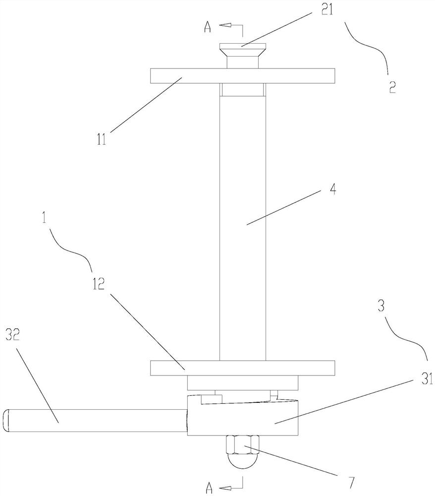
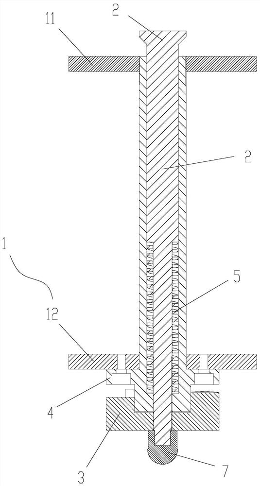
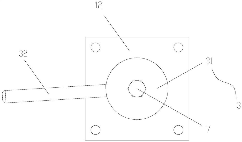
[0029] Such as Figure 1 to Figure 9 As shown, the present invention provides a compression mechanism for relatively compressing or loosening between the first component to be compressed 10 and the second component to be compressed 20. The compression mechanism includes: a compression assembly 1, The pressing assembly 1 includes a first pressing part 11 and a second pressing part 12 arranged at intervals, and the first pressing part 11 and the second pressing part 12 are used for pressing the second part 20 to be pressed; the shaft core 2 , the shaft core 2 is provided with an annular boss 21, and the shaft core 2 is movably mounted on the first pressing member 11 and the second pressing membe...


PUM


Abstract

The invention provides a pressing mechanism, a manipulator and an automatic production line. The pressing mechanism enables a first to-be-pressed piece and a second to-be-pressed piece to be pressed or loosened, and the pressing mechanism comprises a pressing assembly, a central spindle and a rotating part. The pressing assembly comprises a first pressing piece and a second pressing piece so as topress the second to-be-pressed piece. The central spindle is movably arranged on the pressing assembly in a penetrating mode along the axis of the central spindle. The first pressing piece is arranged between the second pressing piece and the annular boss of the central spindle, and the first to-be-pressed piece is arranged between the annular boss and the first pressing piece. The rotating partis arranged on the side, where the pressing assembly is away from the annular boss, on the central spindle, and the distance between the end face, close to the pressing assembly, of the rotating partand the pressing assembly is gradually reduced in the circumferential direction of the central spindle. A supporting column between the pressing assembly and the rotating part is fixed relative to thepressing assembly and abuts against the end face. The rotating part is rotated to enable the supporting column to make contact with the position, with the large or small distance from the pressing assembly, on the end face so that the annular boss can get close to or get away from the pressing assembly, and the problem that clamps on an automatic production line in the prior art are difficult toswitch rapidly is solved.

Description

technical field [0001] The invention relates to the field of automated production, in particular to a pressing mechanism, a manipulator and an automated production line. Background technique [0002] The three-dimensional automated production line needs to replace the mold and tooling when switching products. The mold is a complete set of replacement, and the tooling must also be quickly switched and positioned accurately. [0003] However, when changing the mold, fast positioning cannot be achieved between the positioning plate on the mold side and the mounting bracket on the X-axis of the three-dimensional manipulator, resulting in longer time for mold replacement and lower production efficiency. Contents of the invention [0004] The main purpose of the present invention is to provide a pressing mechanism, a manipulator and an automatic production line, so as to solve the problem in the prior art that it is difficult to quickly switch the clamps on the automatic product...

Claims


Application Information

Patent Timeline
IPC IPC(8): B25J15/00B25J15/08
CPCB25J15/00B25J15/08
Inventor 李亮贺腾飞曾锦桢周惠婷郑海强宋家涛
Owner ZHUHAI GREE INTELLIGENT EQUIP CO LTD
Why Eureka
Try Eureka