
Rotary detection table

A technology of rotating detection and rotating table, which is applied to measuring devices, measuring instrument components, rotary conveyors, etc., can solve the problems of occupying a large space, lengthening the length of the detection line, disordered order, etc., and achieves the goal of improving work comfort. Effect

Pending Publication Date: 2021-03-30
永卓防务科技有限公司
View PDF0 Cites 0 Cited by
  • Summary
  • Abstract
  • Description
  • Claims
  • Application Information

AI Technical Summary

Problems solved by technology

[0003] A large number of mechanical components are required in blasting engineering, and most of them need to be inspected for their quality. However, traditional component inspection devices adopt a linear batch inspection method, which will not only lengthen the length of the inspection line, but also occupy a relatively large area. Large space, at the same time, the order is easy to be confused, and then there will be missed inspections, which will leave hidden dangers

Method used


Image

  • Rotary detection table
  • Rotary detection table
  • Rotary detection table

Examples


Embodiment Construction

[0024] Next, the technical solutions in the embodiments of the present invention will be described in the following examples, and the described embodiments are merely, and embodiments are intended to be, in rather than all embodiments. Embodiments in the present invention, those of ordinary skill in the art will belong to the scope of the present invention in all other embodiments obtained without making creative labor.

[0025] In the description of the present invention, it is to be noted that the term "top", "bottom", "one side", "other side", "front", "behind", "intermediate part", "internal", " The orientation or positional relationship indicated by the top "," bottom ", etc. is based on the orientation or positional relationship shown in the drawings, is merely intended to describe the present invention and simplified description, rather than indicating or implying that the device or component must have The specific orientation is constructed and operated in a specific orien...


PUM


Abstract

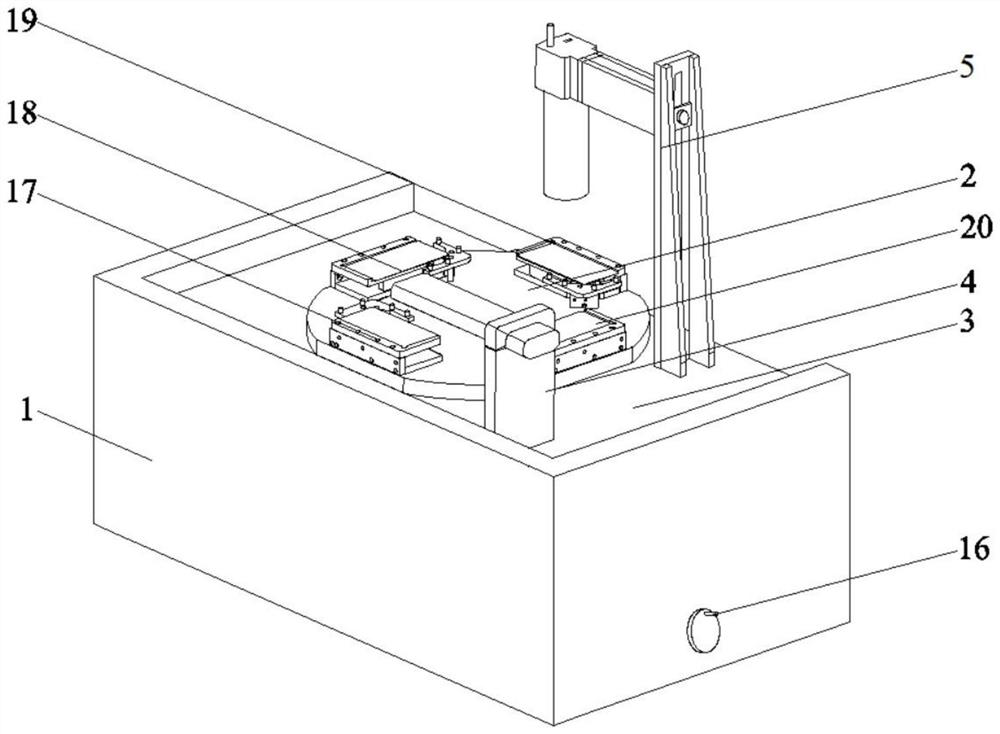
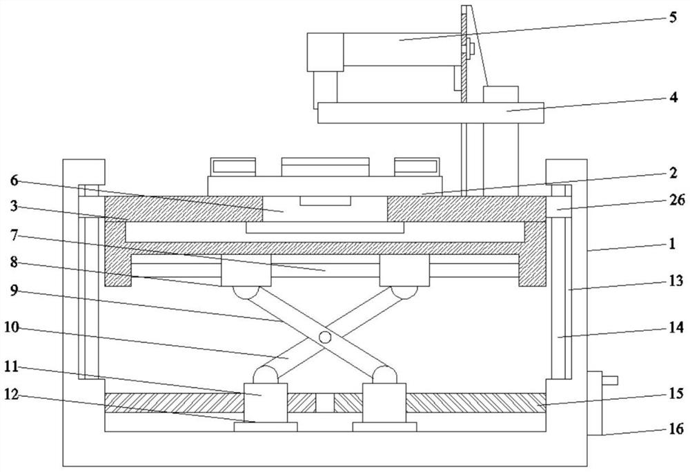
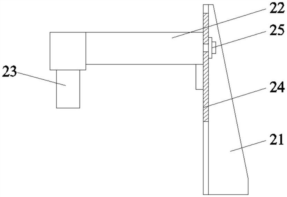
The invention discloses a rotary detection table. The rotary detection table comprises a base and a rotary table, wherein a lifting table is arranged in the base, a rotary air cylinder is arranged inthe center in the lifting table, the output end of the top of the rotary air cylinder is connected with the rotary table, and a feeding table, a transition table, a detection table and a discharging table are sequentially arranged on the top of the rotary table clockwise, a detection mechanism is arranged on the right side of the top of the liftable table, a sliding column is transversely arrangedat the bottom of the lifting table, adjusting sliding sleeves are slidably connected to the two sides of the sliding column in a sleeving mode, a first lifting supporting rod and a second lifting supporting rod are hinged to the bottom faces of the adjusting sliding sleeves on the two sides correspondingly and hinged to each other, lead screw sleeves are hinged to the bottom ends of the first lifting supporting rod and the second lifting supporting rod correspondingly, and the two lead screw sleeves are connected to lead screws arranged at the bottom end of the interior of the base in a threaded and sleeving mode correspondingly. According to the rotary detection table, a component is detected in a rotary detection discharging mode, the size of a detection area is greatly reduced, missingdetection is avoided, the height of the detection table can be freely adjusted, and the comfort degree is higher.

Description

Technical field [0001] The present invention relates to the field of mechanical components, and in particular, to a rotary detecting station. Background technique [0002] In large projects such as railways, mines, reservoirs, the role of blasting technology is very important. The mine road is excavated, and the city's demolition of old buildings will use blasting technology. With the development of the economy, the increase in engineering construction, blasting has caused more attention. As a science and technology, the application is very wide, but in the engineering application is undoubtedly the most important, most common, mining mountain, repairing the railway, road drill explosion to dig the tunnel, the water conservancy project is also used, the city Also used, remove the building. The huge energy produced by explosive explosion destroys the original structure of a certain object. This "destroying" effect is not other method, which is not independently completing a projec...

Claims


Application Information

Patent Timeline
Patent Type & Authority Applications(China)
IPC IPC(8): B65G29/00B65G41/00B65G47/82G01D11/00
CPCB65G29/00B65G41/001B65G47/82B65G2812/14G01D11/00
Inventor 盛开来贾伟龙杨勇明许伟高钰林赵丽
Owner 永卓防务科技有限公司
Learn More