
T-shaped beam template for roads and bridges

A beam formwork, road and bridge technology, applied in bridges, bridge materials, bridge construction, etc., can solve the problem of affecting the forming quality and efficiency of T-shaped beams, affecting the transmission stability of side forms and bases, and blocking the damaged areas of inconvenient formwork, etc. problems, to achieve the effect of convenient and quick installation and disassembly, improving efficiency and quality, and convenient and quick demoulding

Inactive Publication Date: 2021-03-30
谢淦
View PDF0 Cites 1 Cited by
  • Summary
  • Abstract
  • Description
  • Claims
  • Application Information

AI Technical Summary

Problems solved by technology

[0003] However, when laying mountainous roads with many rivers, T-beams with a small span of 5-10 meters are often used for laying, which requires mass production of small T-beams, while traditional T-beams The formwork slides between the formwork and the base through the electric hydraulic cylinder to realize the installation and disassembly between the side form and the bottom form. The stability of the sliding between the side form and the base is poor. At the same time, for the traditional T-beam formwork after use The storage of the formwork takes up space, and it is inconvenient to clean the inside of the formwork. During mass production, concrete waste is easily stuck in the gap between the side formwork and the base during the sliding process of the formwork, which affects the stability of the transmission between the side formwork and the base. At the same time, when the formwork is damaged, it is not convenient to seal the damaged area of ​​the formwork, which in turn affects the quality and efficiency of the T-beam forming

Method used


Image

  • T-shaped beam template for roads and bridges
  • T-shaped beam template for roads and bridges
  • T-shaped beam template for roads and bridges

Examples


Embodiment Construction

[0027] In order to make the technical means, creative features, goals and effects achieved by the present invention easy to understand, the present invention will be further described below in conjunction with specific embodiments.

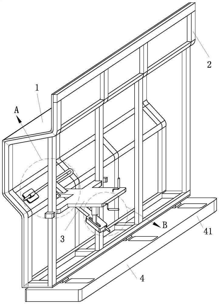
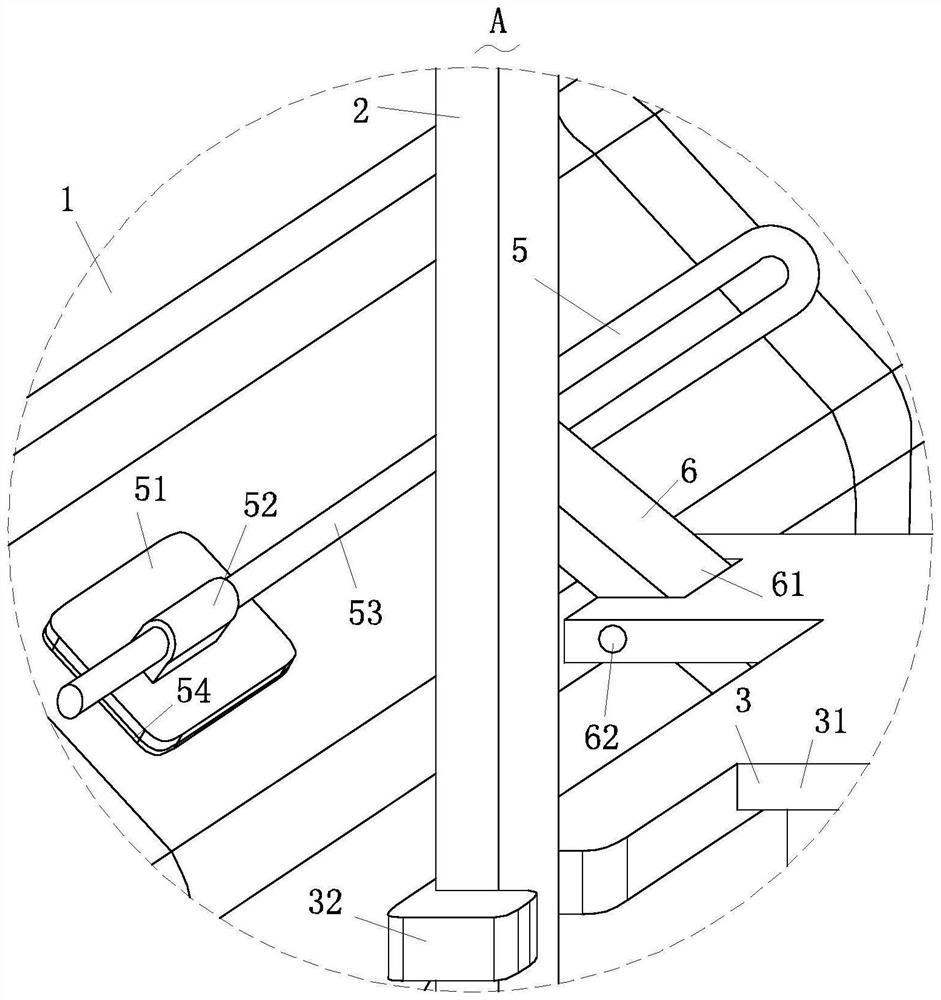
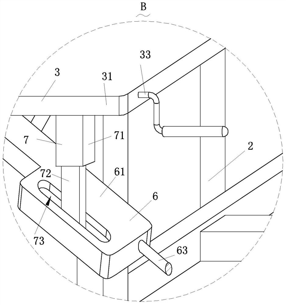
[0028] Such as Figure 1-Figure 8 As shown, a T-beam formwork for a road and bridge according to the present invention includes a formwork body 1, a support frame 2, a fixing structure 3, a guiding structure 4, a blocking structure 5, a transmission structure 6, a driving structure 7, and a booster structure 8 and cleaning structure 9; the formwork body 1 for pouring T-beams is provided with the support frame 2, and the bottom end of the support frame 2 is provided with the guide for adjusting the horizontal position of the support frame 2 Structure 4, the inside of the guide structure 4 is provided with the pressurization structure 8 for pressurizing the airflow, the pressurization structure 8 is connected to the cleaning structure 9 for cleaning...


PUM


Abstract

The invention relates to the field of T-shaped beam templates for roads and bridges and particularly relates to a T-shaped beam template for roads and bridges. The beam template comprises a template body, a support frame, a fixing structure, a guide structure, a blocking structure, a transmission structure, a driving structure, a pressurizing structure and a cleaning structure, therefore, in the process that the guide structure drives the supporting frame and the guide structure to slide, the guide structure drives the pressurizing structure to pressurize air flow, the cleaning structure cleans scraps in the guide structure, transmission of the guide structure is more stable, and operation stability is greatly improved; a blocking structure used for abutting against and sealing the formwork body is arranged at the end of the transmission structure, so the fixing structure is conveniently connected to the supporting frame through the fixing structure, meanwhile, the transmission structure is conveniently driven through the driving structure, and the transmission structure drives the blocking structure to abut against the formwork body; and therefore, the damaged area on the templatebody can be conveniently blocked, and pouring efficiency and quality are greatly improved.

Description

technical field [0001] The invention relates to the field of T-beam formwork for roads and bridges, in particular to a T-beam formwork for roads and bridges. Background technique [0002] T-shaped beam refers to a beam with a T-shaped cross-section. The protruding part on both sides is called the flange, and the middle part is called the beam rib (or web), because it is equivalent to the bending strength of the rectangular beam. The concrete in the tension area is excavated and formed, which is exactly the same as the original rectangular bending strength, but it can save concrete, reduce the weight of the component, and improve the spanning ability. During the production process of the T-beam, the concrete It is poured into the T-beam formwork, and then demoulded after finalizing to form a T-beam prefabricated part. [0003] However, when laying mountainous roads with many rivers, T-beams with a small span of 5-10 meters are often used for laying, which requires mass produ...

Claims


Application Information

Patent Timeline
Patent Type & Authority Applications(China)
IPC IPC(8): E01D21/00E01D2/00E01D101/26
CPCE01D2/00E01D21/00E01D2101/26
Inventor 谢淦张辉
Owner 谢淦
Learn More