Switching device

A technology of switch device and magnetic switch, which is applied in the direction of protection switch, emergency protection device, parts of protection switch, etc., and can solve the problem of switch wear and other problems

Pending Publication Date: 2021-03-30
EPCOS AG
View PDF3 Cites 0 Cited by
  • Summary
  • Abstract
  • Description
  • Claims
  • Application Information

AI Technical Summary

Problems solved by technology

However, this microswitch, like every mechanical switch, is subject to the usual wear and tear

Method used


Image

  • Switching device
  • Switching device
  • Switching device

Examples


Embodiment Construction

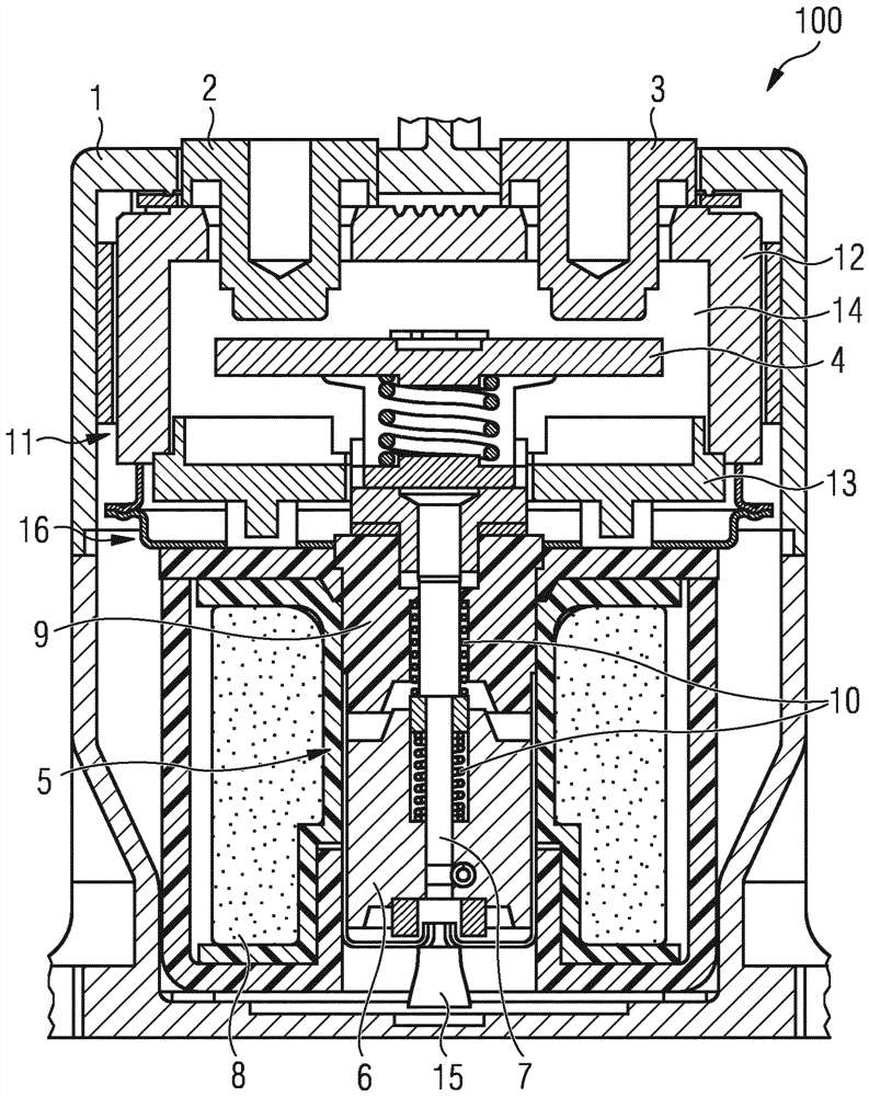
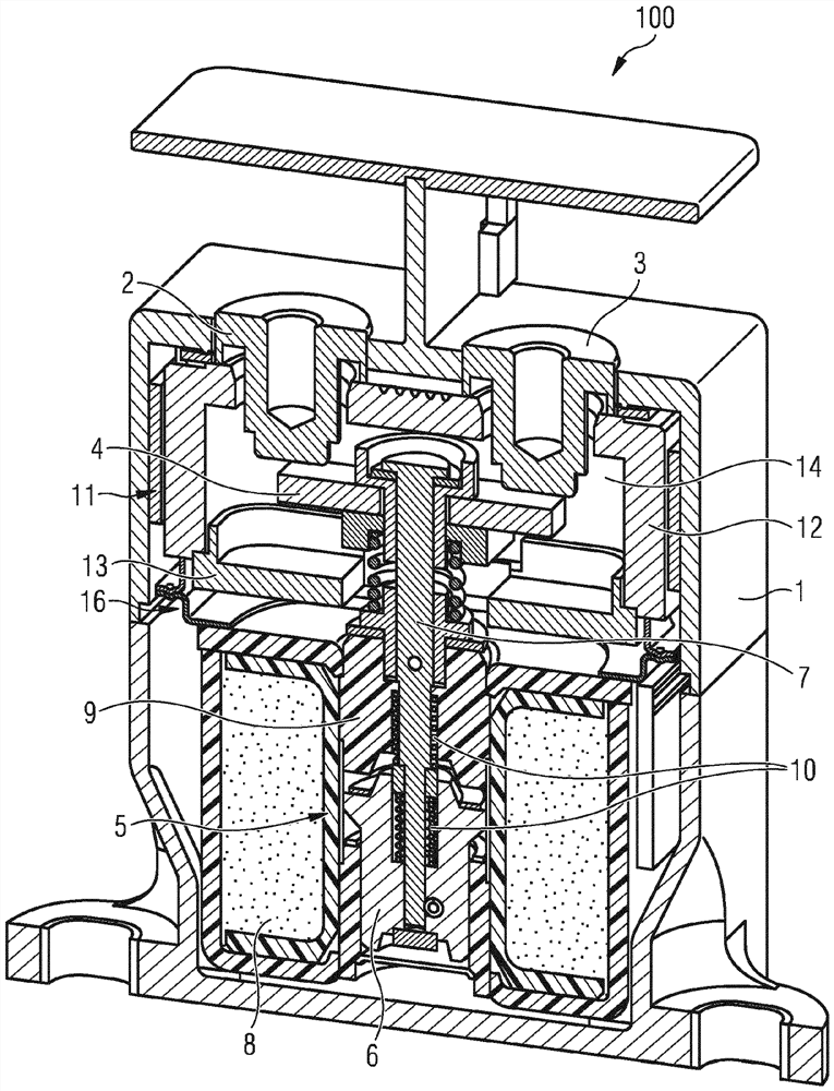
[0033] exist Figure 1A with 1B shows a switching device 100 which can be used, for example, for switching high currents and / or high voltages and which can be a relay or a contactor, in particular a power contactor. Figure 1A shows a three-dimensional cross-sectional view, while Figure 1B A two-dimensional cross-sectional view is shown. The following description also refers to Figure 1A with Figure 1B . The shown geometries are to be understood as exemplary only and not limiting, and alternative configurations are also possible.

[0034] The switching device 100 has two fixed contacts 2 , 3 and one movable contact 4 in the housing 1 . The movable contact 4 is designed as a contact plate. The fixed contacts 2 , 3 together with the movable contact 4 form a switching contact. As an alternative to the number of contacts shown, other numbers of fixed and / or movable contacts are also possible. The housing 1 serves in particular as a touch protection for components arranged...


PUM


Abstract

The invention relates to a switching device (100) comprising at least one stationary contact (2, 3), a movable contact (4), an armature (5), a permanent magnet (17), and a solenoid-operated switch (19), wherein the movable contact can be moved by the armature, the permanent magnet is secured to the armature, and the solenoid-operated switch is a Hall switch.

Description

technical field [0001] The invention proposes a switching device. Background technique [0002] The switching device is designed, in particular, as an electromagnetically-operated, remote-actuated switch that can be operated by means of an electrically conducted current. The switching device can be activated via the control current loop and can switch the load current loop. In particular, the switching device can be designed as a relay or as a contactor, in particular as a power contactor. Particularly preferably, the switching device can be designed as a gas-filled power contactor. [0003] A possible application of such a switching device, in particular a power contactor, is to open and disconnect a battery current circuit, for example in motor vehicles, such as motor vehicles with electric or partially electric operation. These vehicles can be, for example, purely battery-operated vehicles (BEV: "Battery Electric Vehicle"), hybrid electric vehicles (PHEV: "Plug-in Hybr...

Claims


Application Information

Patent Timeline
IPC IPC(8): H01H1/20H01H47/00H01H51/28H01H50/02H01H71/04
CPCH01H1/20H01H2050/025H01H47/002H01H51/28H01H2071/048H01H2071/042H01H71/04H01H50/023
Inventor A·格鲁纳克T·克林格
Owner EPCOS AG
Why Eureka
Try Eureka