Moving mechanism of mobile contact net, mobile contact net and operation method

A mobile mechanism and catenary technology, applied in the direction of overhead lines, etc., can solve the problems of high line use conditions, high cost, poor structural reliability, etc., and achieve the effect of eliminating construction errors and the effects of thermal expansion and cold contraction

Pending Publication Date: 2021-04-02
LANZHOU XINWEI VEHICLE EQUIP CO LTD
View PDF0 Cites 0 Cited by
  • Summary
  • Abstract
  • Description
  • Claims
  • Application Information

AI Technical Summary

Problems solved by technology

At present, a rigid movable catenary system is used, but the existing rigid movable catenary system is extremely expensive, has a complex structure, is inconvenient to install, has high requirements on the use conditions of the line, and has poor structural reliability; it uses a motor to drive the rotating bracket to rotate. Drive the moving section of the overall mobile catenary to move sideways to the side of the rail. In this way, the busbar is installed as a whole at the end of the rotating bracket. There are many motors and it is difficult to control the synchronization of the motor or electric push rod drive.

Method used


Image

  • Moving mechanism of mobile contact net, mobile contact net and operation method
  • Moving mechanism of mobile contact net, mobile contact net and operation method
  • Moving mechanism of mobile contact net, mobile contact net and operation method

Examples


Embodiment Construction

[0050] Reference will now be made in detail to the exemplary embodiments, examples of which are illustrated in the accompanying drawings. When the following description refers to the accompanying drawings, the same numerals in different drawings refer to the same or similar elements unless otherwise indicated. The implementations described in the following exemplary examples do not represent all implementations consistent with the present invention. Rather, they are merely examples of means consistent with aspects of the invention as recited in the appended claims.

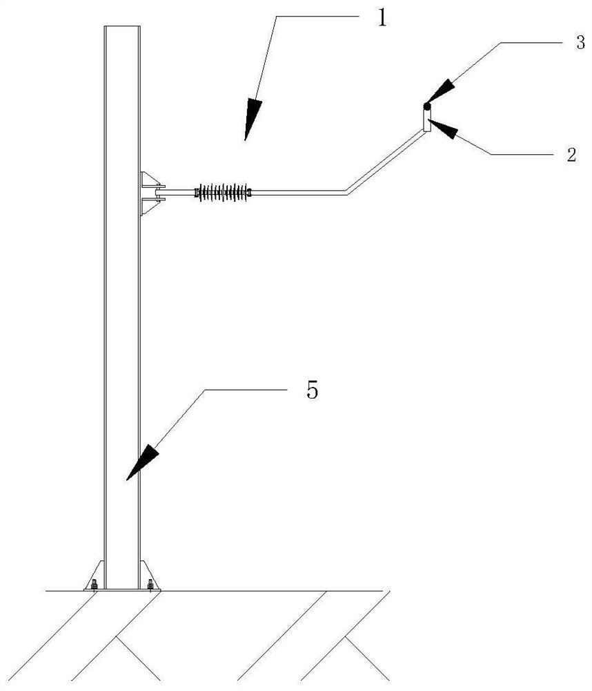
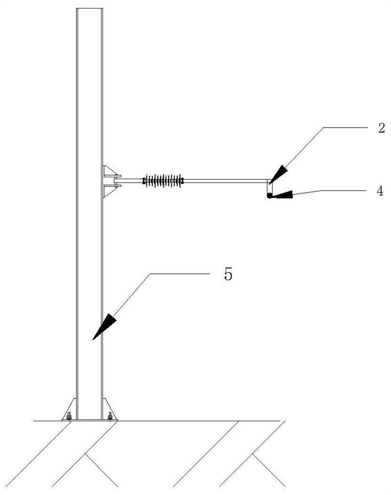
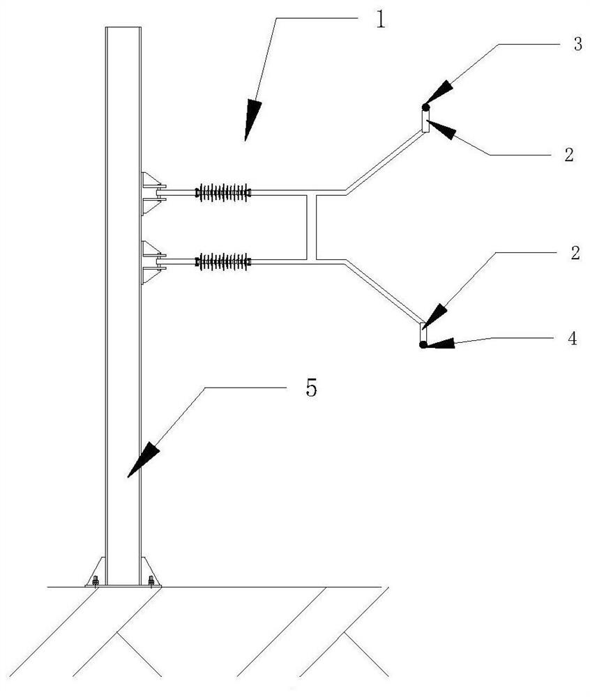
[0051] Such as figure 1As shown, this embodiment provides a moving mechanism for a mobile catenary, including a wrist-arm structure 1 and a sliding mechanism 2, and also includes a catenary 3 and / or a contact wire 4; the traditional method is to connect the catenary 3 and the contact The line 4 is fixed on the rotating arm. In the present invention, the catenary cable 3 and / or the contact line 4 is not fixed on ...


PUM


Abstract

The invention relates to a moving mechanism of a mobile contact network, the mobile contact network and an operation method. The moving mechanism comprises a cantilever structure and a sliding mechanism, and further comprises a carrier cable and/or a contact line; the carrier cable and/or the contact line move/moves relative to the cantilever structure through a sliding mechanism; an included force transmission mechanism is used for indirectly or directly acting thrust or tension formed in the moving process of the carrier cable and/or the contact line or the sliding mechanism on the cantilever structure so as to push or pull the cantilever structure to rotate; and the cantilever structure rotates, thrust or tensile force is formed through the force transmission mechanism and directly or indirectly acts on the sliding mechanism, and therefore the carrier cable and/or the contact line are/is driven to move.

Description

technical field [0001] The invention belongs to the field of electrified railway mobile catenary, and in particular relates to a moving mechanism of a mobile catenary, a mobile catenary and an operation method. Background technique [0002] With the advancement of railway electrification traction, electric locomotives are used to replace diesel locomotives in the transportation of China's main railway lines. Electrification is realized in the cargo handling line or storage maintenance. At present, a rigid movable catenary system is used, but the cost of the existing rigid movable catenary system is extremely high, the structure is complex and inconvenient to install, the requirements for the use of the line are high, and the structural reliability is poor; it uses a motor to drive the rotating bracket to rotate. Drive the moving section of the overall mobile catenary to move sideways to the side of the rail. In this way, the bus bar is installed at the end of the rotating b...

Claims


Application Information

Patent Timeline
Patent Type & Authority Applications(China)
IPC IPC(8): B60M1/20B60M1/22
CPCB60M1/20B60M1/22
Inventor 李彦华张友卢学飞孙永刚于国亮赵文辉
Owner LANZHOU XINWEI VEHICLE EQUIP CO LTD
Why Eureka
Try Eureka