Power box

A technology for power boxes and box doors, applied to electrical components, substation/switch layout details, building fastening devices, etc., can solve problems such as unsafe use, detachment of lock levers, easy unlocking, etc., to improve the safety of use, Improve the effect of user experience

Inactive Publication Date: 2021-04-02
徐冰
View PDF5 Cites 0 Cited by
  • Summary
  • Abstract
  • Description
  • Claims
  • Application Information

AI Technical Summary

Problems solved by technology

[0002] The power box in the prior art generally includes a box body and a box door. The box body includes an outer box body and an inner box body. A heat-insulating cavity is formed between the outer box body and the inner box body. A handle is provided on the front of the box door. The left side of the box is movably connected to the left side of the inner box through a hinge, and the right side of the box door is provided with an inward connecting edge. After the box door is installed in place, the connecting edge touches the right side of the inner box, that is, the power box The connecting side realizes the installation and positioning of the box door, and the locking bar realizes the locking of the position of the connecting side, and then realizes the locking of the box door. However, in the actual use process, the locking bar is often misoperated and separated from the connecting side, resulting in unsafe use. , so it is urgent to optimize the locking structure of the box door to prevent the lock bar from being easily unlocked under the action of misoperation

Method used


Image

  • Power box
  • Power box
  • Power box

Examples


Embodiment 1

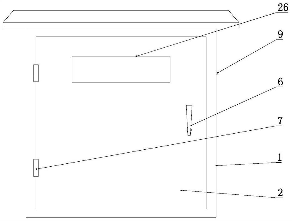
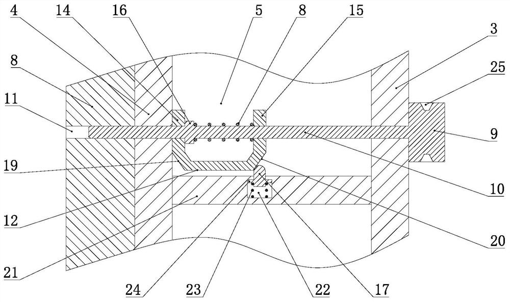
[0019] Example 1: Please refer to Figure 1-Figure 2 , the safe-to-use power box in the embodiment of the present invention includes a box body 1 and a box door 2, the box body 1 includes an outer box body 3 and an inner box body 4, the inner box body 4 is used for placing electrical components, etc., and the outer box body 3 An insulating cavity 5 is formed between the inner box 4 and the inner box 4, so that the inner box 4 is less affected by the temperature of the external links. The left side of the box body 4 is movably connected, and the right side of the box door 2 is provided with an inward connecting edge 8. The connecting edge 8 is formed by folding inward from the right side of the box door 2. After the box door 2 is installed in place, the connecting edge 8 is connected to the inner side. The right side of the box body 4 is in contact with the right side of the outer box body 3, and the right side of the outer box body 3 is provided with a lock button 9. It may be...

Embodiment 2

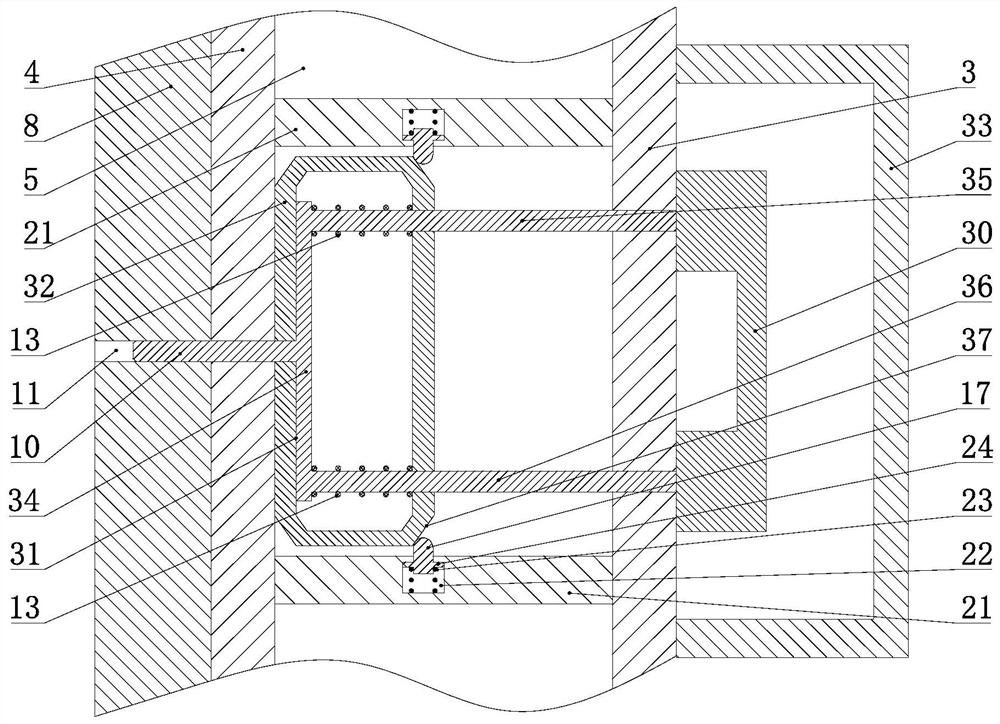
[0022] Embodiment 2: What is different from Embodiment 1 is that combined with image 3 In this embodiment, a lock handle 30 is provided on the right side of the outer box 3, and a lock frame 31 is connected to the left side of the lock handle 30. The lock frame 31 is slidably fitted with a positioning seat 32 and a resistance spring 13. The seat 32 and the resistance spring 13 are located in the heat insulating cavity 5 , the left side of the lock frame 31 is connected with the lock rod 10 , the lock frame 31 abuts the left side of the positioning seat 32 under the action of the resistance spring 13 and isolates the lock rod 10 from The hot cavity 5 and the inner box 4 extend into the locking hole 11 of the connecting edge 8 . In this embodiment, a lock frame 31 , a positioning seat 32 and a resistance spring 13 are added between the lock handle 30 and the lock rod 10 , so that when the lock handle 30 is pulled outward, the lock must be overcome after the resistance spring 13...


PUM


Abstract

The invention discloses a power box. The power box comprises a box body and a box door, wherein the box body comprises an outer box body and an inner box body, and a heat insulation cavity is formed between the outer box body and the inner box body; a connecting edge abuts against the right side of the inner box body after the box door is arranged in place, the connecting edge is provided with a lock hole, the right side of the outer box body is provided with a lock handle, and the left side of the lock handle is connected with a lock frame; and a positioning seat and a resistance spring are connected to the lock frame in a sliding fit mode, the lock frame, the positioning seat and the resistance spring are located in the heat insulation cavity, a lock rod is connected to the left side ofthe lock frame, and the lock frame abuts against the left side of the positioning seat under the action of the resistance spring and enables the lock rod to extend into the lock hole of the connectingedge from the heat insulation cavity and the inner box body. According to the power box, due to the fact that the lock frame, the positioning seat and the resistance spring are additionally arrangedbetween the lock handle and the lock rod, when the lock handle is pulled outwards, the lock frame and even the lock rod can be pulled only after the action of the resistance spring is overcome firstly, the lock rod is not prone to unlock, and the use safety of a user is improved.

Description

technical field [0001] The invention relates to the field of electric power technology, in particular to an electric power box. Background technique [0002] A power box in the prior art generally includes a box body and a box door. The box body includes an outer box body and an inner box body. An insulating cavity is formed between the outer box body and the inner box body. The front of the box door is provided with a handle. The left side of the box is movably connected to the left side of the inner box through a hinge, and the right side of the box door is provided with an inward connecting edge. The connection side realizes the installation and positioning of the box door, and the lock lever is used to lock the position of the connection side, thereby realizing the lock of the box door. However, in the actual use process, the lock lever is often misoperated and separated from the connection side, resulting in unsafe use. Therefore, it is urgent to optimize the locking s...

Claims


Application Information

Patent Timeline
IPC IPC(8): E05B15/00E05B65/52E05C1/10H02B1/46
CPCE05B15/00E05B65/523E05C1/10H02B1/46
Inventor 徐冰
Owner 徐冰
Why Eureka
Try Eureka