Cooling fin self-punching equipment for CPU radiator

A heat sink and self-punching technology, applied in heat exchange equipment, metal processing equipment, feeding devices, etc., can solve the problems of time-consuming and high production costs, and achieve the effect of fully automated operation

Active Publication Date: 2021-04-06
山东西努克机械科技有限公司
View PDF5 Cites 5 Cited by
  • Summary
  • Abstract
  • Description
  • Claims
  • Application Information

AI Technical Summary

Problems solved by technology

[0004] In order to overcome the shortcomings of time-consuming and high production costs, the technical problem of the present invention is to provide a self-punching device for heat sinks for CPU radiators that frees hands and improves productivity

Method used


Image

  • Cooling fin self-punching equipment for CPU radiator
  • Cooling fin self-punching equipment for CPU radiator
  • Cooling fin self-punching equipment for CPU radiator

Examples


Embodiment 1

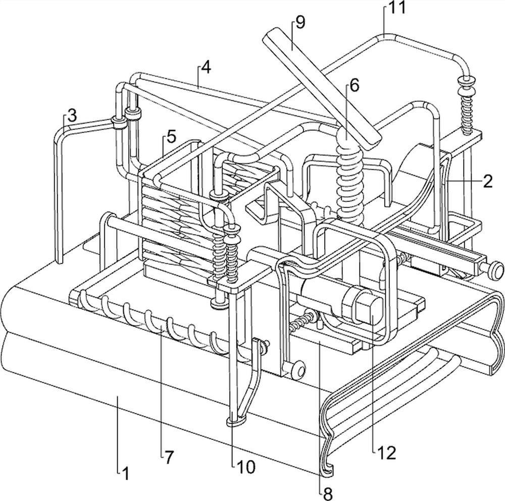
[0061] A kind of heat sink self-punching equipment for CPU heat sink, such as figure 1 As shown, it includes a first support base 1, a first support frame 2, a second support frame 3, a third connecting support frame 4, a discharge frame 5 and a punching mechanism 6, and the upper front side of the first support base 1 is provided with The first support frame 2, the left and right sides of the first support base 1 rear portion are symmetrically provided with the second support frame 3, the first support frame 2 rear portion is provided with a discharge frame 5, and the discharge frame 5 front and rear sides are connected with a third The supporting frame 4 is connected, the third supporting frame 4 is connected with the second supporting frame 3 , and the punching mechanism 6 is slidably provided on the first supporting frame 2 .

[0062] When people need to punch holes for the heat sink, they can use the heat sink self-punching equipment for the CPU heat sink. First, people p...

Embodiment 2

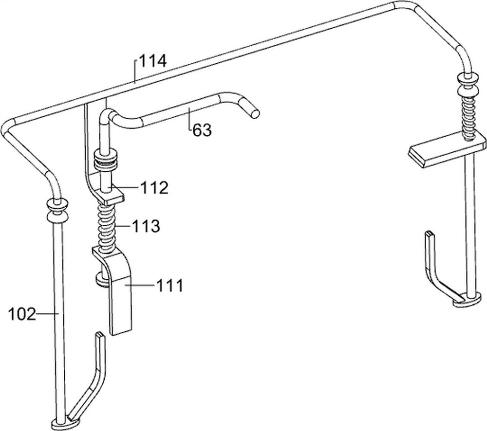
[0064] On the basis of Example 1, such as figure 2As shown, the punching mechanism 6 includes a punching device 61, a first spring 62 and a first round bar 63, and the sliding type is provided with a punching device 61 on the first support frame 2, and the punching device 61 and the first support frame 2 is connected with a first spring 62, and the first spring 62 is wound on the knife punching device 61, and a first round bar 63 is connected to the rear side of the top of the knife punching device 61.

[0065] First, people place the heat sink directly under the knife puncher 61, and then manually move the first round bar 63 downward, so that the knife puncher 61 moves downward, and the first spring 62 is compressed, which realizes punching the heat sink. Operation, when punching is not needed, the first round bar 63 is released, and the first spring 62 drives the puncher 61 to reset, so that the first round bar 63 resets.

Embodiment 3

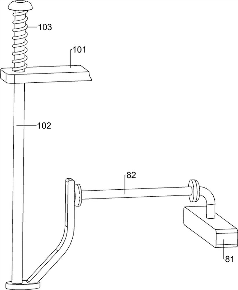
[0067] On the basis of Example 2, such as Figure 3-8 As shown, it also includes a feeding mechanism 7, the feeding mechanism 7 includes a pusher 71, a push rod 72, a second spring 73 and a second round bar 74, and the first support frame 2 slides on the left side and is provided with a pusher. Material rod 72, pusher rod 72 rear portion is connected with pusher 71, is connected with second spring 73 between the first support frame 2 and pusher 71, and second spring 73 is wound on the pusher rod 72, pushes material The right side of the device 71 is provided with a second round bar 74 .

[0068] People manually move the push rod 72 forward, and the second spring 73 is compressed, so that the pusher 71 pushes the heat sink under the discharge frame 5 to move forward, so that the second round bar 74 moves forward, which realizes The effect of feeding, when feeding is completed, people unclamp push rod 72, and second spring 73 drives push rod 72 to reset, and push rod 72 drives ...


PUM


Abstract

The invention relates to punching equipment, in particular to cooling fin self-punching equipment for a CPU radiator. According to the cooling fin self-punching equipment for the CPU radiator, the two hands are liberated, and the productivity is improved. The cooling fin self-punching equipment for the CPU radiator comprises a first supporting frame, second supporting frames, a discharging frame, third connecting supporting frames and a punching mechanism. The first supporting frame is arranged on the upper portion of a first supporting base. The second supporting frames are symmetrically arranged on the two sides of the first supporting base. The discharging frame is arranged on the first supporting frame. The two sides of the discharging frame are connected with the third connecting supporting frames, and the third connecting supporting frames are connected with the second supporting frames. The punching mechanism is arranged on the first supporting frame in a sliding manner. According to the cooling fin self-punching equipment, a cooling fin is placed under a punching cutter device by people, then a first round block rod is manually moved downwards, the punching cutter device is made to move downwards, and a first spring is compressed.

Description

technical field [0001] The invention relates to a punching device, in particular to a self-punching device for a heat sink for a CPU heat sink. Background technique [0002] The heat sink is a device for cooling the heat-prone electronic components in electrical appliances. It is mostly made of aluminum alloy, brass or bronze into plates, sheets, and multi-sheets. For example, the CPU central processing unit in a computer needs to use a large Therefore, it is necessary to punch the heat sink. At present, the punching method is mostly manual punching with a hand-held machine. This method is repetitive manual labor, wastes time, consumes physical strength, and has high production costs. [0003] In order to free people's hands, improve productivity, and manufacture suitable heat sinks, we need to design an automatic self-punching equipment for heat sinks for CPU heat sinks that integrates punching, feeding and clamping. Contents of the invention [0004] In order to overcom...

Claims


Application Information

Patent Timeline
Patent Type & Authority Applications(China)
IPC IPC(8): B21D28/26B21D28/04B21D53/04B21D43/02
CPCB21D28/26B21D28/04B21D53/04B21D43/02Y02D10/00
Inventor 李翠兰
Owner 山东西努克机械科技有限公司
Why Eureka
Try Eureka