Booster pump fastening and pipeline connecting structure of water purifier with double-cavity structure

A technology of booster pump and cavity structure, applied in water/sewage treatment, water/sewage multi-stage treatment, water/sewage treatment equipment and other directions, can solve the problem that water purifiers are difficult to popularize more widely, and achieve a simple appearance and structure Beautiful appearance, simple structure setting and pipeline connection, simple and convenient fixing structure

Pending Publication Date: 2021-04-06
杜宁峻
View PDF6 Cites 0 Cited by
  • Summary
  • Abstract
  • Description
  • Claims
  • Application Information

AI Technical Summary

Problems solved by technology

However, since the upper operating surface and the central core position of the machine are used for the setting of the above-mentioned basic functions, in the limited space structure range of the machine size of about 500mm×200mm×460mm, the setting position, connection and fixing structure around the booster pump Mode, related pipeline connections, booster pump circuit control, and pipeline and water storage structure settings of the concentrated water reuse system, as well as the fixed structure of related water-passing electric control components, and convenient connection of pipelines, so that the machine-related water-power The setting and installation of the control parts and structures, especially the fastening and connection around the booster pump have caused a series of new problems
The above-mentioned defects and deficiencies cause the water purifier to be difficult to be more widely popularized

Method used


Image

  • Booster pump fastening and pipeline connecting structure of water purifier with double-cavity structure
  • Booster pump fastening and pipeline connecting structure of water purifier with double-cavity structure
  • Booster pump fastening and pipeline connecting structure of water purifier with double-cavity structure

Examples


Embodiment 1

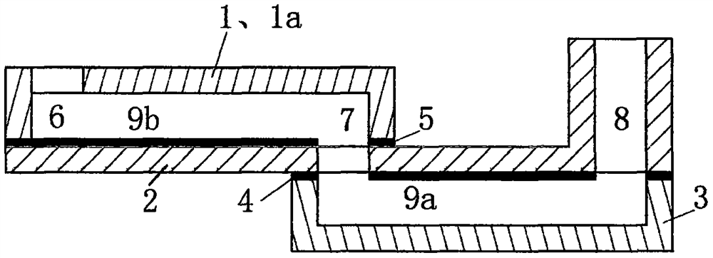
[0019] Example 1. A booster pump fastening and pipeline connection structure for a water purifier with a double-cavity structure, including a water-passing pipeline connected in series to multiple filters including a pre-filter and a reverse osmosis membrane filter, and a booster pump The part corresponding to the pre-filter is the pre-filter channel and the water inlet electric control valve is set. The water inlet and outlet pipes of the booster pump are respectively connected to the rear end of the pre-filter channel and the inlet of the reverse osmosis membrane filter. Water port; the reverse osmosis membrane filter gallbladder pure water port is connected to the pure water pipeline, the reverse osmosis membrane filter gallbladder drain outlet is connected to the concentrated water discharge pipeline of the concentrated water discharge flow control device, and is located at the concentrated discharge water discharge end of the concentrated water flow control device. In the...

Embodiment 2

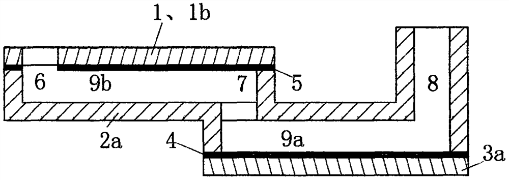
[0021] Example 2. On the basis of Example 1, the frame structure is provided with a downwardly extending screw support; one end is fixed on the lower end surface of the base of the gallbladder cavity by a screw, and the other end is horizontally extended and suspended in the double-layer U-shaped pipeline The structure is connected with the screw support by screws to form a whole.

[0022] As an improvement, the frame structure is provided with downwardly extending screw supports. The front end of the double-layer U-shaped pipe structure extending laterally and suspended in the air is connected with the screw support to form a whole through screws, so as to ensure that the intubation structure with the front end of the double-layer U-shaped pipe structure facing upward cooperates with the booster pump The plug-in fit of the relevant nozzle connection downward intubation structure has a stable working condition, and can withstand high water pressure in the pipe and is not affe...

Embodiment 3

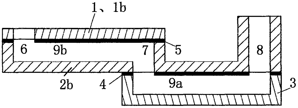
[0023] Example 3. A booster pump fastening and pipeline connection structure for a water purifier with a double-cavity structure, including a water-passing pipeline connected in series to multiple filters including a pre-filter and a reverse osmosis membrane filter, and a booster pump The part corresponding to the pre-filter is the pre-filter channel and the water inlet electric control valve is set. The water inlet and outlet pipes of the booster pump are respectively connected to the rear end of the pre-filter channel and the inlet of the reverse osmosis membrane filter. Water port; the reverse osmosis membrane filter gallbladder pure water port is connected to the pure water pipeline, the reverse osmosis membrane filter gallbladder drain outlet is connected to the concentrated water discharge pipeline of the concentrated water discharge flow control device, and is located at the concentrated discharge water discharge end of the concentrated water flow control device. In the...


PUM


Abstract

The invention relates to the water treatment industry, in particular to the aspect of filtering of drinking water, and discloses a booster pump fastening and pipeline connecting structure of a water purifier with a double-cavity structure. The structure comprises a water passing pipeline which is connected with a plurality of filter liners including a front filter liner and a reverse osmosis membrane filter liner in series and a filter channel formed by a booster pump, and a concentrated water discharging pipeline of the reverse osmosis membrane filter liner is provided with a water return pipeline with a concentrated water discharging and storing cavity and a water return electric control valve and connected with a water inlet pipeline of the booster pump; the structure further comprises a high-position assembly pipeline and a low-position assembly pipeline which are arranged in an up-and-down staggered mode and communicated through a through hole, and the high-position assembly pipeline and the low-position assembly pipeline are each provided with an upward external water port which is communicated with the booster pump and a related butt joint water port in the bottom of the filter container cavity. A water inlet and a water outlet of the booster pump are respectively connected with a downward insertion pipe structure to be matched with corresponding double-layer U-shaped pipelines in the double-path double-layer U-shaped pipeline structure in an insertion manner, and are respectively connected with a butt joint water port which is formed in the filter container cavity base and is in butt joint with the rear end of the front filter channel and the water inlet of the reverse osmosis membrane filter container.

Description

technical field [0001] The invention relates to the water treatment industry, and specifically relates to the deep filtration and purification of drinking water. Background technique [0002] The double-chamber structure water purifier composed of a gallbladder chamber for placing the gallbladder and a facility chamber for placing the booster pump has the advantages of easy replacement of the gallbladder by the user and convenient maintenance, especially the gap between the wall of the gallbladder chamber and the built-in gallbladder can be used. The space structure among them stores the concentrated water so as to facilitate the reuse of the concentrated water. However, since the upper operating surface and the central core position of the machine are used for the setting of the above-mentioned basic functions, in the limited space structure range of the machine size of about 500mm×200mm×460mm, the setting position, connection and fixing structure around the booster pump M...

Claims


Application Information

Patent Timeline
Patent Type & Authority Applications(China)
IPC IPC(8): C02F9/02
CPCC02F1/001C02F1/441C02F2201/004
Inventor 不公告发明人
Owner 杜宁峻
Why Eureka
Try Eureka