Knitting machine auxiliary device capable of preventing thread residues clamped in gaps of rotating shafts from being difficult to remove

An auxiliary device and technology of knitting machine, applied in the directions of knitting, weft knitting, warp knitting, etc., can solve the problem that the plush is easily stuck in the gap between the side walls of the rollers, cannot continue to run, and the plush cannot rotate by itself. problems, to avoid off-axis deviation

Inactive Publication Date: 2021-04-06
海宁家辉新材料科技股份有限公司
View PDF0 Cites 0 Cited by
  • Summary
  • Abstract
  • Description
  • Claims
  • Application Information

AI Technical Summary

Problems solved by technology

[0003] Most of the knitted products are made of thread segments with plush material. During the rotation between the rollers of the knitting machine, the sidewalls of these thread segments will pass through the sidewalls of the rollers, and the remaining wool The velvet will easily get stuck in the gap between the side walls of the rollers, and some velvet cannot be turned out by itself. If it accumulates too much, it will easily cause the side walls of the rollers to get stuck and cannot continue to run.

Method used


Image

  • Knitting machine auxiliary device capable of preventing thread residues clamped in gaps of rotating shafts from being difficult to remove
  • Knitting machine auxiliary device capable of preventing thread residues clamped in gaps of rotating shafts from being difficult to remove
  • Knitting machine auxiliary device capable of preventing thread residues clamped in gaps of rotating shafts from being difficult to remove

Examples


Embodiment Construction

[0021] The following will clearly and completely describe the technical solutions in the embodiments of the present invention with reference to the accompanying drawings in the embodiments of the present invention. Obviously, the described embodiments are only some, not all, embodiments of the present invention. Based on the embodiments of the present invention, all other embodiments obtained by persons of ordinary skill in the art without making creative efforts belong to the protection scope of the present invention.

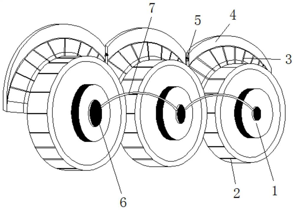
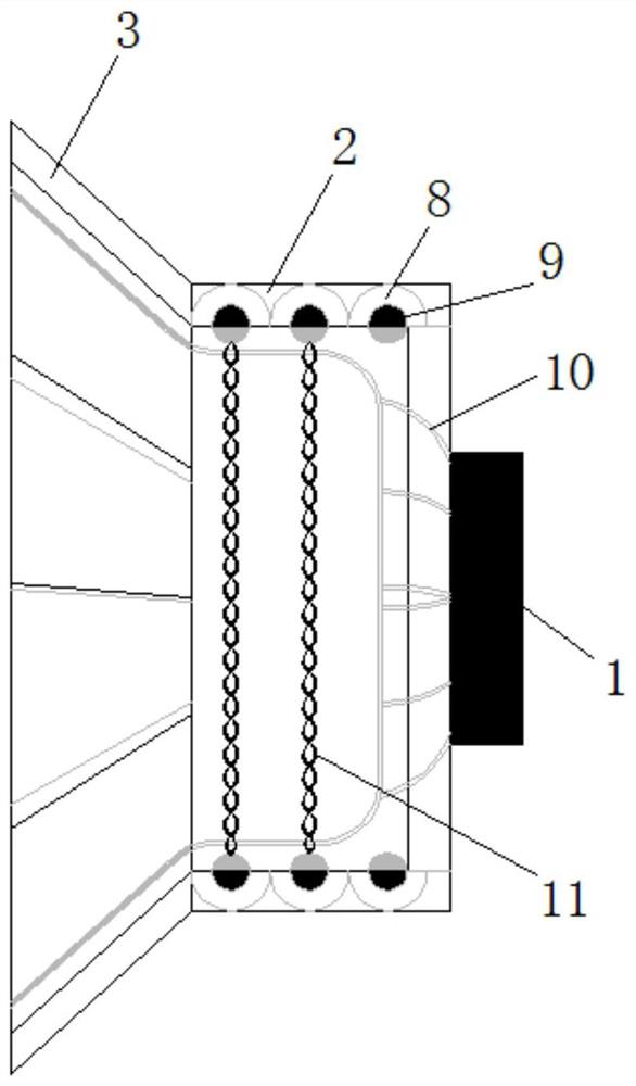
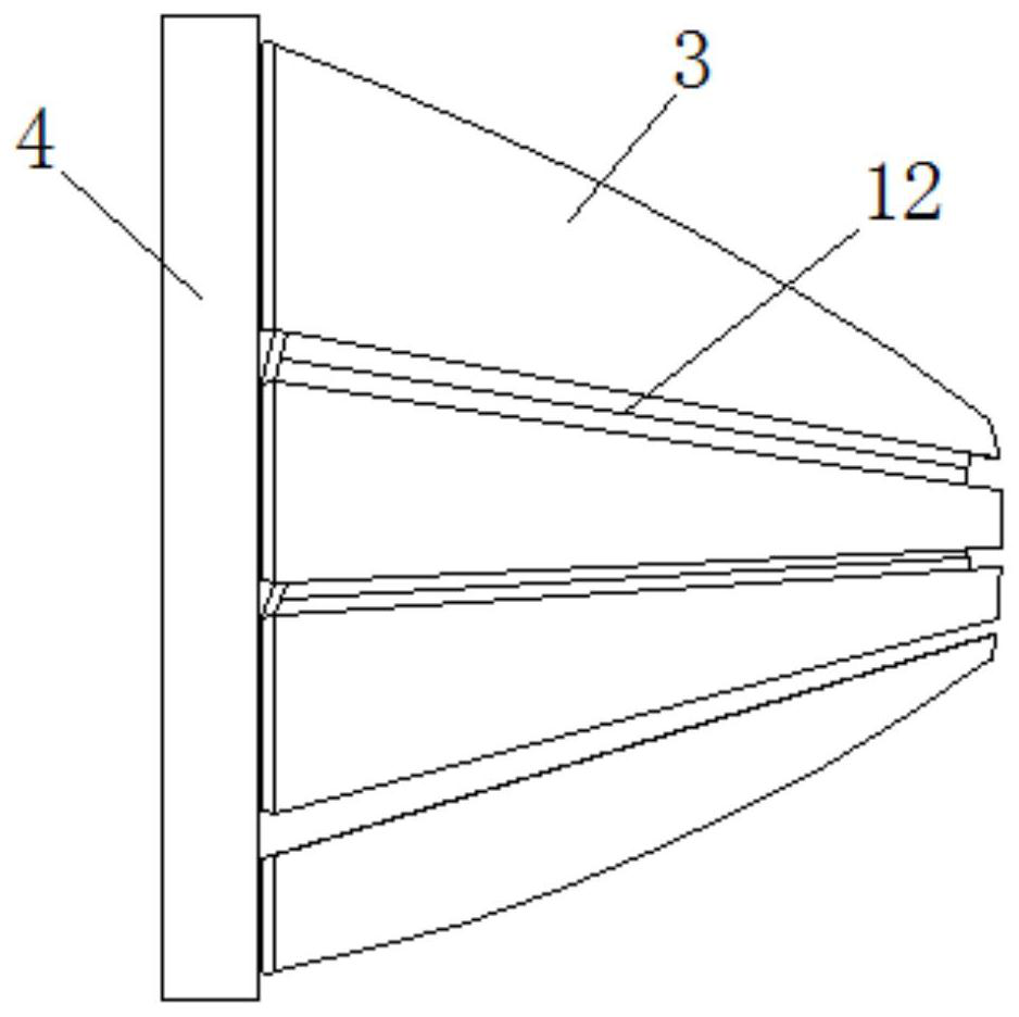
[0022] see Figure 1-4 , an auxiliary device for knitting machines that prevents thread ends from being stuck in the gaps of the rotating shaft and is difficult to remove, comprising a movable shaft 1, a rotating shaft 6 is arranged at the axis of the side wall of the moving shaft 1, and a connecting belt 7 is fixedly connected to the side wall of the rotating shaft 6, A turntable 2 runs through the side wall of the movable shaft 1, a gripper 10 runs through t...


PUM


Abstract

The invention relates to the technical field of knitting machines, and discloses a knitting machine auxiliary device capable of preventing thread residues clamped in gaps of rotating shafts from being difficult to remove. The knitting machine auxiliary device comprises movable shafts, the axes of the side walls of the movable shafts are provided with rotating shafts, the side walls of the rotating shafts are fixedly connected with connecting belts, and rotary discs penetrate through the side walls of the movable shafts; grippers penetrate through the inner axes of the rotary discs, rotary shells penetrate through the inner sides wall of the rotary discs, and rolling shafts penetrate through the axes of the side walls of the rotary shells. According to the knitting machine auxiliary device capable of preventing the thread residues clamped in the gaps of the rotating shaft from being difficult to remove, the side walls of the rotary discs can drive the adjacent rotary discs on the side walls of the rotary discs to rotate together, and when the side walls of the rotary discs rotate, the side walls of the movable shafts can be driven to rotate together, so that the connecting belts connected to the axes of the movable shafts can be driven to rotate along with the movable shafts, and the side walls of the movable shafts can be pulled at intervals; therefore, the side walls of the rotating discs can be limited to a certain extent in the rotating process, off-axis deviation in the rotating process is avoided, and the situation that loosening occurs after a long time is also avoided.

Description

technical field [0001] The invention relates to the technical field of knitting machines, in particular to an auxiliary device for knitting machines that prevents thread ends from being stuck in the gaps of rotating shafts and is difficult to remove. Background technique [0002] The knitting machine can replace manpower to make knitted products by hand, which can avoid the time-consuming and labor-intensive production of fewer finished products, and also meet the large demand in the market. There are many styles, and the artificial hand-made fabrics cannot guarantee the uniformity of the patterns. It is also impossible to ensure that the size of the thread holes is uniform between the side walls of the object, and there may be asymmetry. The knitting machine is easy to operate and can produce products of the same style in a unified manner. [0003] Most of the knitted products are made of thread segments with plush material. During the rotation between the rollers of the kn...

Claims


Application Information

Patent Timeline
IPC IPC(8): D04B15/94D04B27/00D04B35/32
CPCD04B15/94D04B27/00D04B35/32
Inventor 蒋利海
Owner 海宁家辉新材料科技股份有限公司
Why Eureka
Try Eureka