
Rainwater recycling system for hydraulic engineering construction based on water flow potential energy

A technology of water conservancy engineering and water flow potential energy, applied in general water supply conservation, construction, water supply installations, etc., can solve the problems of impurity accumulation, evaporation, low utilization rate of rainwater, etc., to reduce the possibility of evaporation, improve the spray range, and avoid a large number of stacking effect

Inactive Publication Date: 2021-04-06
吴紫娟
View PDF8 Cites 5 Cited by
  • Summary
  • Abstract
  • Description
  • Claims
  • Application Information

AI Technical Summary

Problems solved by technology

[0007] The purpose of the present invention is to provide a rainwater recovery and utilization system for water conservancy construction based on the potential energy of water flow, so as to solve the problem that the current rainwater recovery and utilization equipment on the market proposed by the above-mentioned background technology is inconvenient to filter the rainwater after filtering. Impurities are automatically discharged from the outside of the equipment, which can easily cause a large amount of impurities to accumulate inside the equipment. It is not convenient to automatically close the water inlet when the weather is fine, which will not only easily cause dust and impurities from the outside to enter the inside of the equipment, but also cause excessive external dust and impurities to enter the equipment. The temperature causes the collected rainwater to evaporate, which reduces the overall practicability of the equipment. At the same time, the overall utilization rate of rainwater after rainwater collection and treatment is low

Method used


Image

  • Rainwater recycling system for hydraulic engineering construction based on water flow potential energy
  • Rainwater recycling system for hydraulic engineering construction based on water flow potential energy
  • Rainwater recycling system for hydraulic engineering construction based on water flow potential energy

Examples


Embodiment Construction

[0032] The following will clearly and completely describe the technical solutions in the embodiments of the present invention with reference to the accompanying drawings in the embodiments of the present invention. Obviously, the described embodiments are only some, not all, embodiments of the present invention. Based on the embodiments of the present invention, all other embodiments obtained by persons of ordinary skill in the art without making creative efforts belong to the protection scope of the present invention.

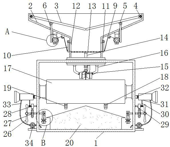
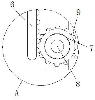
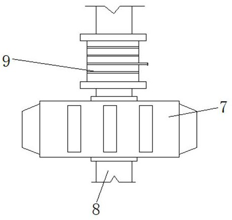
[0033] see Figure 1-10, the present invention provides a technical solution: a rainwater recycling system for water conservancy construction based on water flow potential energy, including a support base 1, a water inlet bucket 2, a protective plate 3, a first vortex spring 4, a sliding block 5, a tooth Plate 6, drive gear 7, central rod 8, traction rope 9, side baffle 10, second scroll spring 11, discharge port 12, filter screen 13, transmission rod 14, bott...


PUM


Abstract

The invention discloses a rainwater recycling system for hydraulic engineering construction based on water flow potential energy. The rainwater recycling system comprises a supporting base, a water inlet hopper, an electromagnetic valve, a water conveying pipe and a water pump, wherein the water inlet hopper is fixedly arranged in the middle of the upper end of the supporting base, a protective plate is arranged inside the water inlet hopper, a filter screen is arranged inside the water inlet hopper, a transmission rod is fixedly arranged in the middle of the lower end of the filter screen, a collecting box is arranged at the lower end of a bottom impeller, the side of the collecting box is fixedly arranged inside the supporting base, the water conveying pipe is arranged at the lower end of a water spraying head, and the water conveying pipe is fixedly arranged on the side of the water pump. According to the rainwater recycling system for hydraulic engineering construction based on the water flow potential energy, impurities after treatment can be conveniently and automatically discharged out of equipment after rainwater is filtered, so that a large amount of impurities are prevented from being accumulated inside, meanwhile, the possibility that the rainwater is evaporated due to the fact that the external temperature is too high is reduced, and the utilization rate of the rainwater can be improved.

Description

technical field [0001] The invention relates to the related technical field of water conservancy projects, in particular to a rainwater recovery and utilization system for water conservancy project construction based on water flow potential energy. Background technique [0002] With the continuous progress of national science and technology, various regions pay more and more attention to the construction of water conservancy projects. Water conservancy projects are various construction projects built to control, utilize and protect surface and underground water resources. In the process of water conservancy project construction, in order to be effective To reduce the waste of water resources, rainwater is usually recycled and stored in rainy days, so that it can be used later in the construction of water conservancy projects. Therefore, rainwater recovery devices are mostly used in rainwater collection. [0003] However, the current rainwater recycling equipment has the foll...

Claims


Application Information

Patent Timeline
Patent Type & Authority Applications(China)
IPC IPC(8): E03B3/02E01H3/04B01D29/03B01D29/74B01D29/94
CPCE03B3/02E01H3/04B01D29/03B01D29/74B01D29/94B01D2221/12Y02A20/108
Inventor 吴紫娟
Owner 吴紫娟
Learn More