A cyclic shear fatigue testing machine

A technology of fatigue testing machine and specimen, which is applied in the direction of testing material strength by applying stable shear force, testing material strength by applying repetitive force/pulsation force, instruments, etc. The accuracy of the test data is greatly affected, and there are no universal applicability of materials, etc., to achieve the effect of simple and reliable loading method, shielding deformation, and cost saving

Active Publication Date: 2022-05-17
SHANDONG UNIV
View PDF7 Cites 0 Cited by
  • Summary
  • Abstract
  • Description
  • Claims
  • Application Information

AI Technical Summary

Problems solved by technology

[0003] For the cyclic shear fatigue performance test of materials, due to many interference factors in the test process, the accuracy of the test data is not high
In the testing test of the prior art, the commonly used method is to form the test piece and the test machine into an integral structure, but due to the existence of the gap between the test sample and the test device, in the process of repeated loading, the application of the load is different from the actual The value does not match, which makes it have a greater impact on the accuracy of the test data, which is the main bottleneck of the material shear fatigue performance test
Therefore, the test method for cyclic shear fatigue performance of materials is also very limited and does not have universal applicability of materials

Method used


Image

  • A cyclic shear fatigue testing machine
  • A cyclic shear fatigue testing machine
  • A cyclic shear fatigue testing machine

Examples


Embodiment Construction

[0024] In order to make the technical problems, technical solutions and advantages to be solved by the present invention clearer, a detailed and complete description will be given below in conjunction with the accompanying drawings and specific embodiments.

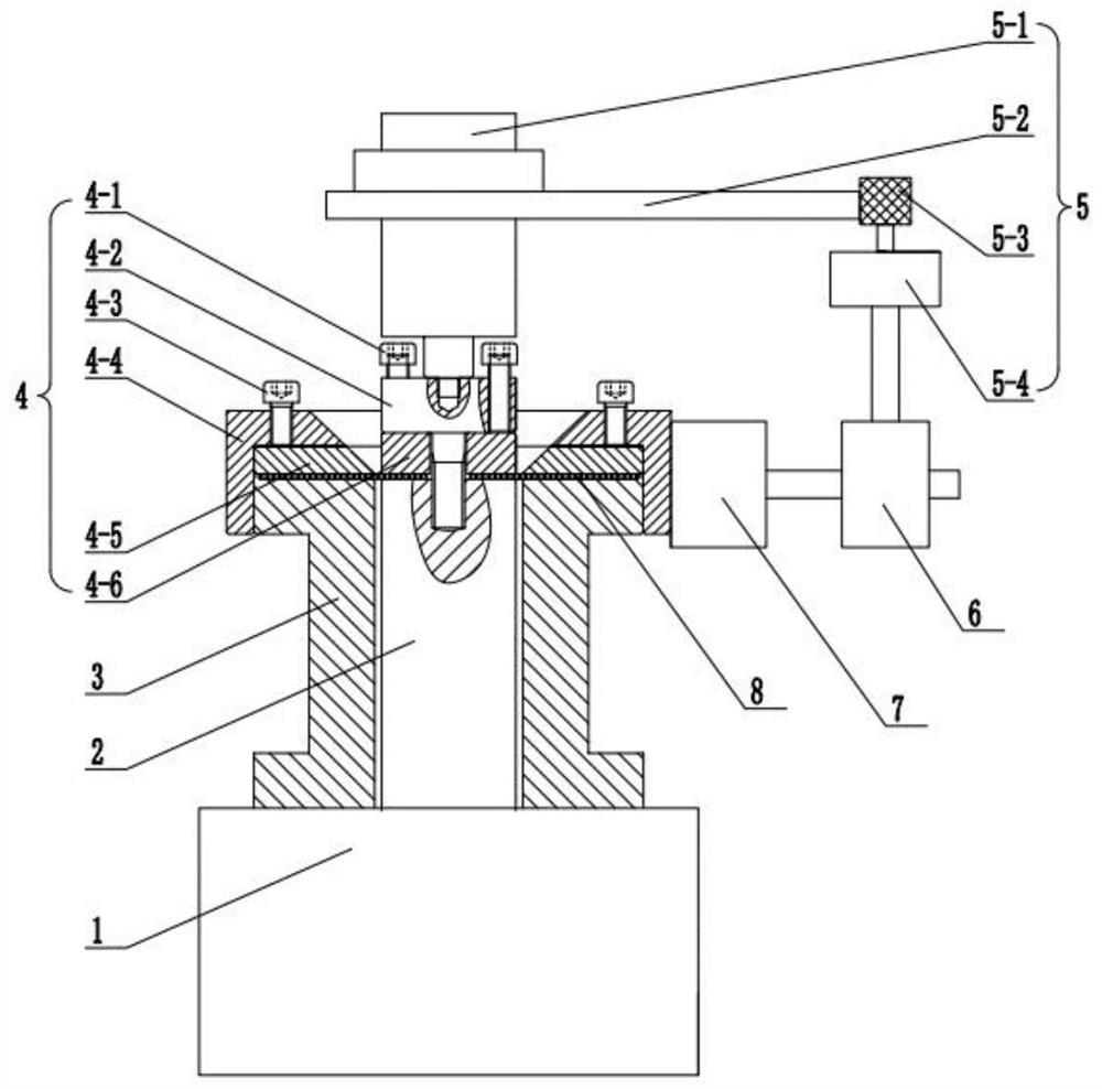
[0025] The invention provides a cyclic shear fatigue testing machine, such as figure 1 As shown, it includes a link base 1, a power shaft 2, a rotation torque sensor 3, a specimen clamping mechanism 4, and a specimen rotation angle acquisition mechanism 5, wherein:

[0026] The lower end of the power rotating shaft 2 is fixedly connected with the reducer in the link base 1, the cylindrical outer wall of the upper end of the rotation torque sensor 3 is provided with threads, and the lower surface of the rotation torque sensor 3 is in contact with the upper surface of the link base 1 and is fixedly connected by bolts;

[0027] The upper end surface of the power rotating shaft 2 and the upper end surface of the rotational to...


PUM


Abstract

The invention discloses a cyclic shear fatigue testing machine, which belongs to the field of material testing. The cyclic shear testing machine includes a link base, a power shaft, a rotational torque sensor, a specimen clamping mechanism, and a specimen rotation angle collection mechanism, wherein: the power shaft is fixedly connected to a reducer in the link base, and the rotation The torque sensor is located above the link base and fixedly connected with the link base. The specimen clamping mechanism includes an outer clamping mechanism and an inner clamping mechanism. The outer clamping mechanism and the inner clamping mechanism are located above the power shaft and are respectively connected to the rotating The torque sensor is fixedly connected to the power shaft, and the specimen rotation angle acquisition mechanism includes a follower shaft, a turntable, a reading wheel, and an encoder. The follower shaft is located above the inner clamping device and is fixedly connected to the inner clamping device. The turntable is fixedly connected with the follower shaft, and the reading wheel is located above the encoder. The invention is applied to the material fatigue test and solves the problem of plate cyclic shearing.

Description

technical field [0001] The invention relates to the field of material shear fatigue performance testing, in particular to a cyclic shear fatigue testing machine. Background technique [0002] At present, in the field of practical engineering applications, metal materials are usually used as structural materials for load bearing, but during their service period, due to the dynamic load, especially the cyclic shearing action, the performance of the material is reduced and the service life is reduced. Therefore, the shear fatigue performance of the material under cyclic shear loading must be determined for the evaluation of the strength performance of the necessary structural details. [0003] For the cyclic shear fatigue performance test of materials, due to many interference factors in the test process, the accuracy of the test data is not high. In the testing test of the prior art, the commonly used method is to form the test piece and the test machine into an integral stru...

Claims


Application Information

Patent Timeline
Patent Type & Authority Patents(China)
IPC IPC(8): G01N3/24G01N3/32G01N3/04
CPCG01N3/24G01N3/32G01N3/04G01N2203/0025G01N2203/0073
Inventor 岳振明张中然张帅苏联朋岳义伟高军
Owner SHANDONG UNIV
Why Eureka
Try Eureka