
Intelligent pressure relief valve and using method

A release valve, intelligent technology, applied in the direction of functional valve type, safety valve, balance valve, etc., can solve problems such as non-action, pressure relief valve can not protect the transformer operation well, mechanical parts response delay, etc.

Active Publication Date: 2021-04-09
STATE GRID SHANDONG ELECTRIC POWER +2
View PDF8 Cites 0 Cited by
  • Summary
  • Abstract
  • Description
  • Claims
  • Application Information

AI Technical Summary

Problems solved by technology

[0004] The current pressure relief valve relies on the action of mechanical parts to complete the pressure release process, and the instantaneous oil flow surge will cause instantaneous oil pressure changes during the operation of the transformer, and there is a response delay in the action of mechanical parts, or it cannot be sensed Instantaneous oil pressure changes and then no action, so that the pressure relief valve can not protect the operation of the transformer well

Method used


Image

  • Intelligent pressure relief valve and using method
  • Intelligent pressure relief valve and using method
  • Intelligent pressure relief valve and using method

Examples


Embodiment 1

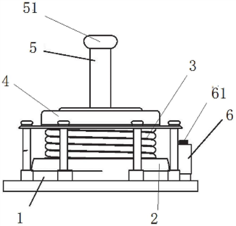
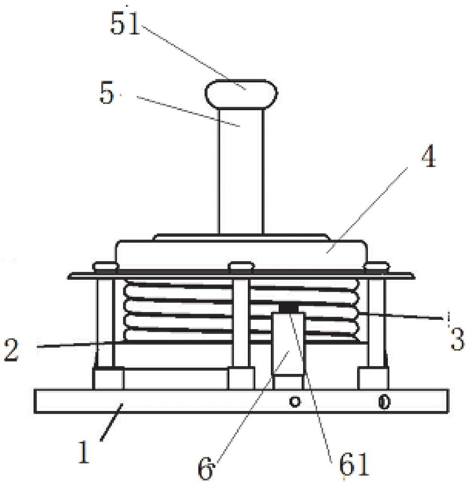
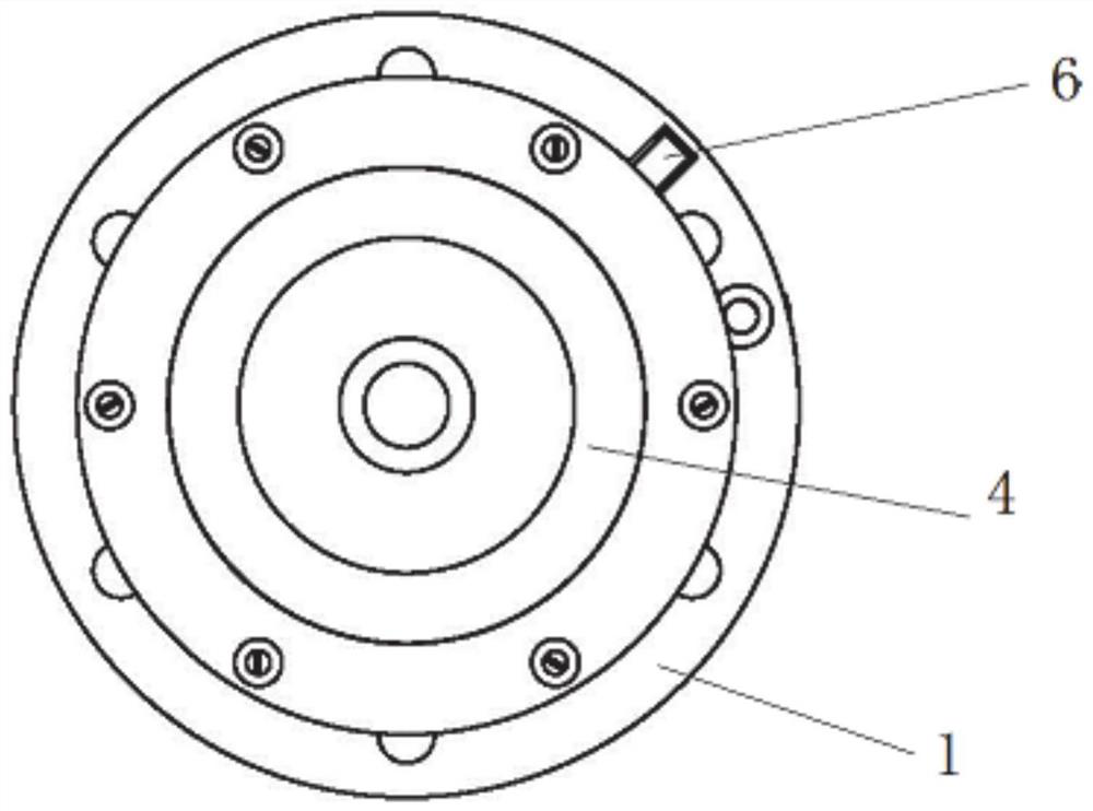
[0030] Such as Figure 1-3 As shown, an intelligent pressure relief valve includes a valve seat 1 communicated with the transformer oil tank, an external casing of the valve seat 1, a valve cover on the top of the casing, and a pressure relief port on the casing;

[0031] The valve seat 1 is connected to the spring seat 4 through a fastener, and the direction of the spring seat 4 close to the valve seat 1 is connected to the actuating disk 2 through the spring 5, and the actuating disk 2 is closely attached to the valve seat 1.

[0032] The valve seat 1 has a hollow pressure sensing section 6 . One end of the pressure sensing section 6 has a pressure sensing port 61 , and the other end is connected to the valve seat 1 . The pressure transmitter is connected to the valve seat 1 through the pressure sensing port 61 .

[0033] The pressure transmitter communicates with the transformer oil tank through the pressure taking port 61, the pressure taking section 6 and the valve seat 1...

Embodiment 2

[0043] Here's how to use the above pressure relief valve:

[0044] When the transformer is running, the valve seat 1 communicates with the inside of the transformer oil tank, and the action disc 2 driven by the spring 5 presses the valve seat 1 to seal the transformer oil. When an accident occurs inside the transformer, the oil pressure inside the transformer oil tank rises, and when the pressure limited by the transformer oil to the sealing gasket is greater than the pressure of the spring 5, the actuating disc 2 starts to move upward, separating the actuating disc 2 from the valve seat 1, and then opens The pressure relief valve releases the pressure, and at the same time, the pop-up action plate 2 drives the flag rod 5 to be lifted up, and then drives the flag cap 51 to jack up, indicating that the pressure relief valve is in an open state at this time.

[0045]The transformer oil leaks, and the pressure in the transformer oil tank drops. When the pressure drops to the clo...


PUM


Abstract

The invention relates to an intelligent pressure relief valve which comprises a valve seat communicated with a transformer oil tank, the valve seat is connected with a spring seat through a fastener, the spring seat is connected with an action disc through a spring in a direction close to the valve seat, and the action disc is tightly attached to the valve seat under the action of the spring; and the valve seat is provided with a hollow pressure tapping section, one end of the pressure tapping section is provided with a pressure tapping port, the other end of the pressure tapping section is connected to the valve seat, and a pressure transmitter is connected with the valve seat through the pressure tapping port. Oil pressure value changes are monitored in real time in the transformer fault and operation process, the alarm soft protection function is achieved, early warning is conducted on possible faults in advance, and meanwhile operation and maintenance personnel can analyze the operation state of a transformer according to alarm pressure records stored in a background.

Description

technical field [0001] The invention relates to the field of electric power systems, in particular to an intelligent pressure release valve and its use method. Background technique [0002] Transformer, as a key main power equipment, occupies a pivotal position in the power system, and its stable operation is an important prerequisite to ensure the reliable transmission, flexible distribution and safe use of electric energy in the entire power system. Especially for high-voltage level, large-capacity hub transformers, due to their high cost, complex structure, and large loads, no matter if the protection refuses to operate or malfunctions, it will seriously affect the safe and stable operation of the power system. When a serious fault occurs inside the transformer, the insulating oil vaporizes and decomposes to produce a large amount of gas. Since the main oil tank of an oil-immersed power transformer is similar to a closed container, once the pressure caused by a fault can...

Claims


Application Information

Patent Timeline
Patent Type & Authority Applications(China)
IPC IPC(8): F16K17/04F16K37/00F16K17/164
CPCF16K17/0413F16K37/0091F16K17/164Y02E10/20
Inventor 刘长道张洪东徐磊邵长春李琦王伟哲顾凯旋韩宝国马驰戚祥
Owner STATE GRID SHANDONG ELECTRIC POWER
Learn More