
Optical flow prediction method and device

A prediction method and optical flow technology, applied in the field of computer vision, can solve the problems of poor optical flow estimation in occluded areas, and cannot solve the problem of learning in occluded areas, and achieve the effect of improving accuracy and accuracy.

Pending Publication Date: 2021-04-09
MEGVII BEIJINGTECH CO LTD +1
View PDF0 Cites 2 Cited by
  • Summary
  • Abstract
  • Description
  • Claims
  • Application Information

AI Technical Summary

Problems solved by technology

Such a method can significantly improve the accuracy of optical flow in non-occluded areas, but it cannot solve the learning problem in occluded areas, making the estimation of optical flow in occluded areas less effective.

Method used


Image

  • Optical flow prediction method and device
  • Optical flow prediction method and device
  • Optical flow prediction method and device

Examples


Embodiment Construction

[0061] Embodiments according to the present invention will be described in detail below with reference to the drawings. When the description refers to the drawings, the same reference numerals in different drawings indicate the same or similar elements unless otherwise indicated. It should be noted that the implementations described in the following exemplary embodiments do not represent all implementations of the present invention. They are merely examples of apparatuses and methods consistent with certain aspects of the present disclosure as recited in the claims, and the scope of the present invention is not limited thereto. On the premise of no contradiction, the features in the various embodiments of the present invention can be combined with each other.

[0062] In addition, the terms "first" and "second" are used for descriptive purposes only, and cannot be interpreted as indicating or implying relative importance or implicitly specifying the quantity of indicated techn...


PUM


Abstract

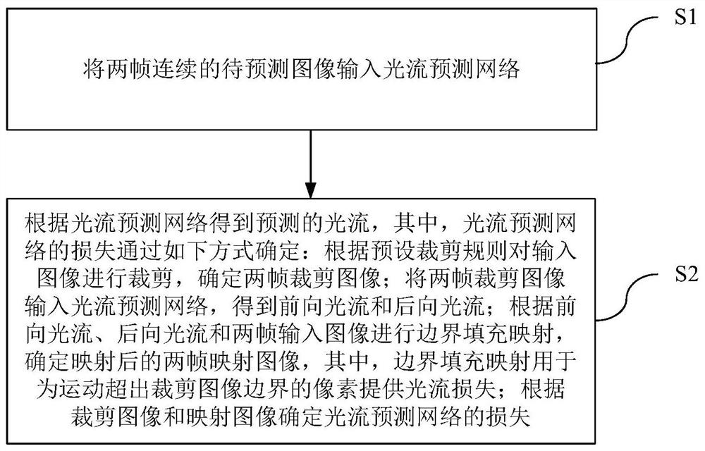
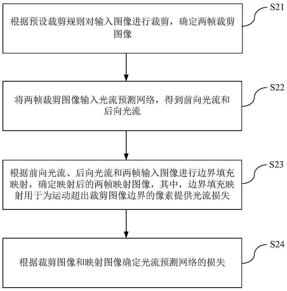
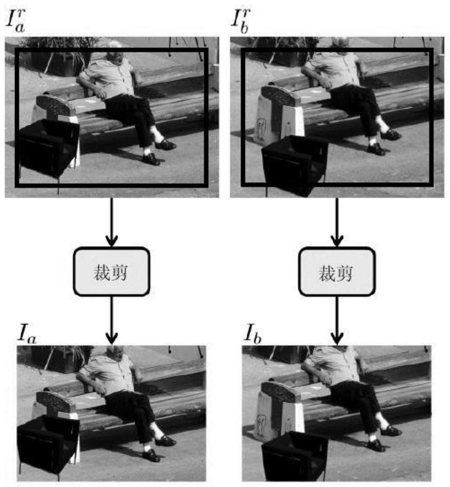
The invention provides an optical flow prediction method and device, and relates to the technical field of computer vision, and the method comprises the steps: inputting two continuous to-be-predicted images into an optical flow prediction network; obtaining predicted optical flow according to the optical flow prediction network, wherein the loss of the optical flow prediction network is determined by the following steps: cutting an input image according to a preset cutting rule, and determining two frames of cut images; inputting the two frames of cut images into an optical flow prediction network to obtain a forward optical flow and a backward optical flow; performing boundary filling mapping according to the forward optical flow, the backward optical flow and the two frames of input images, and determining two frames of mapped images after mapping; and determining the loss of the optical flow prediction network according to the cut image and the mapping image. According to the invention, the boundary filling mapping is carried out on the cut image, so the pixels moving beyond the boundary of the cut image can still be replaced by the corresponding pixels of the input image after the boundary filling mapping, the correct image loss is obtained, and the accuracy of optical flow prediction is improved.

Description

technical field [0001] The present invention relates to the technical field of computer vision, in particular to an optical flow prediction and device. Background technique [0002] With the development of computer technology, the field of computer vision has also developed quite rapidly. Optical flow prediction is a fundamental task in computer vision and plays an important role in many fields such as autonomous driving, video processing, object detection, behavior analysis, etc. In recent years, due to the rise of deep learning, optical flow prediction methods based on deep learning have gradually become mainstream. Existing optical flow prediction methods based on deep learning include FlowNet, FlowNet-v2, PWC-Net, and IRR-PWCNet. Its main advantages are high accuracy, fast speed, fast deployment, and strong generalization. However, the optical flow prediction method based on deep learning has very high requirements for training data, and requires accurate labeling of ...

Claims


Application Information

Patent Timeline
Patent Type & Authority Applications(China)
IPC IPC(8): G06T7/269
CPCG06T7/269G06T2207/10016G06T2207/20081G06T2207/20084
Inventor 罗堃铭叶年进刘帅成
Owner MEGVII BEIJINGTECH CO LTD
Learn More