A laser-based uplink and downlink visible light communication link device

A visible light communication and downlink technology, applied in the field of laser-based uplink and downlink visible light communication link devices, can solve the problem that the device processing speed and storage capacity are difficult to achieve high-speed transmission, the Ethernet transmission network speed is reduced, and the system complexity is increased. and other problems, to achieve the effect of simplifying system integration complexity, stabilizing two-way communication, and avoiding signal reflection

Active Publication Date: 2022-07-19
XIAMEN UNIV +2
View PDF5 Cites 0 Cited by
  • Summary
  • Abstract
  • Description
  • Claims
  • Application Information

AI Technical Summary

Problems solved by technology

[0003] Visible light communication technology uses visible light sources to send out high-speed bright and dark flashing signals to transmit information, and the receiving end receives the transmitted information through the photodetector detection circuit; the traditional system is mainly based on the sending end through DSP or programmable logic device FPGA. Extraction, code mapping, digital modulation and digital demodulation at the receiving end, code demapping and other operations can complete the transmission of Ethernet data; although the transmission of Ethernet frame data can be completed in this way, it is limited by the processing speed and storage capacity of the device. It is difficult to achieve the purpose of high-speed transmission; in addition, if the simultaneous data transmission of uplink and downlink is realized, it will not only increase the complexity of the system, make long-distance transmission difficult, but also greatly increase the bit error rate. In the process, the increase of the bit error rate will lead to the decrease of the Ethernet transmission speed; therefore, it is of great significance to find a practical application circuit that can improve the transmission speed of the Ethernet and can facilitate the simultaneous long-distance transmission of uplink and downlink.

Method used


Image

  • A laser-based uplink and downlink visible light communication link device

Examples


Embodiment Construction

[0025] The following embodiments will further illustrate the present invention in conjunction with the accompanying drawings.

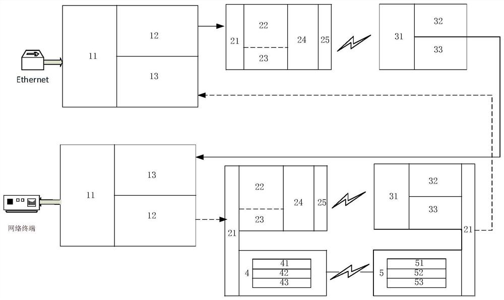
[0026] like figure 1 As shown, the embodiment of the present invention includes an uplink and a downlink; the downlink is provided with an Ethernet signal processing module, a light source driving module and a photoelectric detection module; the Ethernet signal processing module is composed of an Ethernet signal extraction circuit 11. The differential-to-single-ended circuit 12 and the single-ended-to-differential circuit 13 are composed. The light source driving module is composed of a switch 21, a visible light laser driving circuit 22, an infrared laser driving circuit 23, an automatic gain control circuit 24 and a light source 25; The photoelectric detection module is composed of a photodetector APD 31, a leakage protection circuit 32, and a photoelectric detection circuit 33; the Ethernet signal extraction circuit 11 is connected to an Ethernet, ...


PUM


Abstract

A laser-based uplink and downlink visible light communication link device belongs to the field of visible light communication. The data of the Ethernet physical layer is directly extracted through the interface processing hardware circuit, and there is no need to establish the communication network interface between Ethernet and FPGA or DSP, which simplifies the complexity of system integration and reduces the development cycle, and avoids the problem of reducing the rate of visible light communication; The interface processing circuit and the differential-to-single-ended and single-ended-to-differential circuits are integrated into one module to avoid the problems of high-speed signal attenuation and signal reflection during transmission. The automatic power control circuit is integrated in the light source drive circuit of the transmitting end, and the leakage protection is designed in the photoelectric detection circuit of the receiving end; the visible light laser is mainly used for communication in the downlink, so as to realize stable two-way communication, which can meet the practical application at low cost. It meets the requirements of high-speed and long-distance communication transmission of visible light, and meets the performance requirements of other terminal equipment such as home digital network TV for Internet access.

Description

technical field [0001] The invention belongs to the field of visible light communication, in particular to a laser-based uplink and downlink visible light communication link device. Background technique [0002] Visible light communication, as a powerful supplement to the current household fiber optic Internet access, effectively solves the problem of the current depletion of spectrum resources, and the spectrum resources of visible light are very abundant and do not require complex licenses for use; in addition, visible light communication can be used in hospitals and other electromagnetic receivers. It can be used in limited or sensitive areas, and the safety factor is high. As long as the transmission path of visible light is blocked, the signal can be effectively cut off. [0003] The visible light communication technology uses the visible light source to send out high-speed bright and dark flickering signals to transmit information, and the received information is recei...

Claims


Application Information

Patent Timeline
Patent Type & Authority Patents(China)
IPC IPC(8): H04B10/116H04B10/50H04B10/516H04B10/564
CPCH04B10/116H04B10/503H04B10/516H04B10/564
Inventor 吴挺竹王泽平郑振耀张鸣华周海珠刘青青陈传凤陈忠刘梦林岳吕毅军
Owner XIAMEN UNIV
Why Eureka
Try Eureka