
Medical instrument for percutaneous release procedures

A technology of medical devices and procedures, applied in the field of medical devices, can solve problems such as damage to surrounding tissues and structures, complex structures, etc.

Pending Publication Date: 2021-04-09
SWIBRACE SA
View PDF6 Cites 0 Cited by
  • Summary
  • Abstract
  • Description
  • Claims
  • Application Information

AI Technical Summary

Problems solved by technology

[0011] The disadvantage of the medical device disclosed in US Pat. No. 5,782,850A is that its construction is still relatively complicated
In addition, medical devices are constructed such that the groove-like depressions and the hook-like cutting edges extending therein may cause undesired damage to surrounding tissues and structures, especially during the extraction of the medical device

Method used


Image

  • Medical instrument for percutaneous release procedures
  • Medical instrument for percutaneous release procedures
  • Medical instrument for percutaneous release procedures

Examples


no. 1 approach

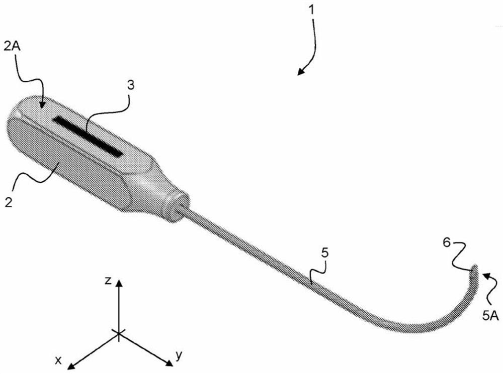
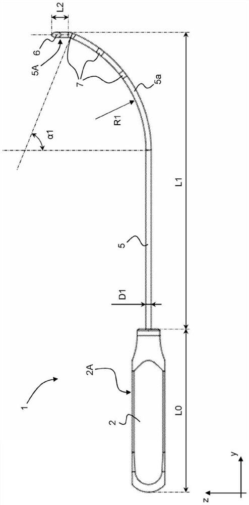
[0187] 2 Handle part of medical device 1, 1*

[0188] 2A Inner face of handle part 2

[0189] 2B Mounting hole provided on the handle part 2 for fastening the elongated rod member 5, 5* (e.g. inserted by mechanical pressing and / or glued)

[0190] 3 Marking on inner face 2A of handle part 2 (eg laser marking)

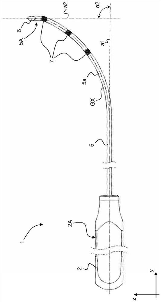
[0191] 5 Elongate rod member of medical device 1 extending in defined plane P0

[0192] 5a (single) curved portion of elongate rod member 5

[0193] 5A End of (second part of) elongate rod member 5

[0194] 6 Angled end, located at the end 5A of the elongated rod member 5, designed as a cutting device for severe tissue

[0195] 6A Inclined surface of inclined end 6

[0196] 7 markings (e.g. embossing) placed along the elongated rod member 5, designed to be discernible under ultrasonic inspection

[0197] 1* Medical device according to the invention (variation of the first embodiment)

[0198] 5* Elongated rod members of medical devices 1* extending in a defined pl...

no. 2 approach

[0235] 20 Handle part of medical device 10, 10*

[0236] 20A Inner face of handle portion 20

[0237] 20B Mounting hole provided on handle portion 20 for securing elongated rod member 50, 50* (eg inserted by mechanical press-in and / or glued)

[0238] 50 Elongate rod member of medical device 10 extending in defined plane P0

[0239] 50a (first) curved portion of elongated rod member 50

[0240] 50b (second) curved portion of elongate rod member 50

[0241] 50c (third) curved portion of elongate rod member 50

[0242] 50A End of (second part of) elongate rod member 50

[0243] 60 Angled end, located at the end 50A of the elongated rod member 50, designed as a cutting device for severe tissue

[0244] 60A sloped surface of sloped end 60

[0245] 70 markings (e.g. embossing) placed along the elongated rod member 50, designed to be discernible under ultrasonic inspection

[0246] 10* Medical device according to the invention (variation of the second embodiment)

[0247] 50*...


PUM


Abstract

A medical instrument (1) for percutaneous release procedures, especially on upper or lower limbs, such as percutaneous carpal tunnel release or percutaneous A1 pulley release. The medical instrument (1) comprises a handle portion (2) designed to allow handling, orientation and manipulation of the medical instrument (1) and an elongated rod member (5) secured to the handle portion (2) and extending within a defined plane (P0). A first portion of the elongated rod member (5) extends along a first direction (al) within the defined plane (PO) away from the handle portion (2), and a second portion of the elongated rod member (5), downstream of the first portion, is curved and / or bent within the defined plane (P0). A free end of the elongated rod member (5), at a terminal end (5A) of the second portion, is shaped as a bevelled end (6) exhibiting a bevelled surface (6A), which bevelled end (6) is designed to act as a cutting device to severe tissue, the bevelled surface (6A) being inclined with respect to the defined plane (P0).

Description

technical field [0001] The present invention relates generally to medical devices for use in percutaneous release procedures, particularly for upper or lower extremity release procedures, such as but not limited to percutaneous carpal tunnel release and percutaneous A1 pulley release. Solution. The present invention is also applicable to other release procedures such as, but not limited to, tenolysis, tenotomy, tenotomy-lengthening, aponeurosis, neurolysis, and neurotomy. [0002] Background of the invention [0003] Carpal tunnel syndrome (CTS) and trigger finger syndrome (TFS) can be conveniently treated with surgical release procedures. These surgical release procedures are usually performed using a simple puncture needle or more complex hook knife or push knife. This medical device can also be used for other surgical release procedures on the upper or lower extremities, such as for the treatment of Morton's neuroma, tarsal tunnel release, de Kravin syndrome, epicondylal...

Claims


Application Information

Patent Timeline
Patent Type & Authority Applications(China)
IPC IPC(8): A61B17/32A61B90/00
CPCA61B17/320036A61B2090/08021A61B2090/3925A61B2017/00455A61B2090/3937A61B2017/00314
Inventor 法比安·穆贡多
Owner SWIBRACE SA
Learn More