
Medical instrument for percutaneous release procedures

a technology of percutaneous release and medical instruments, applied in the field of medical instruments for percutaneous release procedures, can solve the problems of unsatisfactory solutions, unsatisfactory configurations, and unwanted damage to surrounding tissues and structures

Pending Publication Date: 2021-12-02
SWIBRACE SA
View PDF0 Cites 0 Cited by
  • Summary
  • Abstract
  • Description
  • Claims
  • Application Information

AI Technical Summary

Benefits of technology

The invention relates to an elongated rod member used in a medical instrument. The rod member has a thin configuration, with a maximum width of 2 mm, which makes it easy to insert and withdraw the instrument without damaging the surrounding tissues or structures. This feature makes the instrument safer and more efficient in medical procedures.

Problems solved by technology

A drawback of the carpal tunnel tome disclosed in U.S. Pat. No. 5,507,800 A therefore resides in the fact that the associated surgical operation is not strictly percutaneous and still requires a relatively large incision in the palmar side of the patient's hand, which necessitates corresponding sutures to close the incision following the surgical procedure.
A drawback of the solution disclosed in U.S. Pat. No. 5,029,573 A thus resides in the fact that the associated surgical operation is likewise not strictly percutaneous and requires two relatively large incisions in the palmar side of the patient's hand as well as on the wrist to allow insertion of the trocar, which necessitates corresponding sutures to close the relevant incisions following the surgical procedure.
This solution is not satisfying however since the release procedure is not easy to carry out and potentially dangerous for adjacent structures.
A drawback of the medical instrument disclosed in U.S. Pat. No. 5,782,850 A resides in the fact that the configuration thereof is still relatively complex.
Furthermore, the configuration of the medical instrument is such that the groovelike depression and hook-shaped cutting edge extending therein may cause unwanted damage to surrounding tissues and structures, especially during withdrawal of the medical instrument.

Method used


Image

  • Medical instrument for percutaneous release procedures
  • Medical instrument for percutaneous release procedures
  • Medical instrument for percutaneous release procedures

Examples


second embodiment

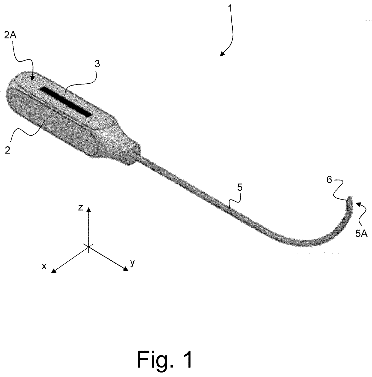
[0106]Referring to FIGS. 11 to 20, there is shown another embodiment of a medical instrument, designated by reference numeral 10, in accordance with the present invention, which other embodiment is particularly suited for percutaneous A1 pulley release in the treatment of the trigger finger syndrome (TFS). A variant of this second embodiment, designated by reference numeral 10*, is further shown in FIGS. 28 to 31.

[0107]Further embodiments of the invention are discussed with reference to FIGS. 32 to 43A-C. FIGS. 32 to 37A-C illustrate a further embodiment of a medical instrument 100 that is particularly suited for percutaneous carpal tunnel release in the treatment of the carpal tunnel syndrome (CTS), while FIGS. 38 to 43A-C illustrate another embodiment of a medical instrument 110 that is particularly suited for percutaneous A1 pulley release in the treatment of the trigger finger syndrome (TFS).

[0108]All embodiments share a number of common features, including a handle portion 2, 2...

first embodiment

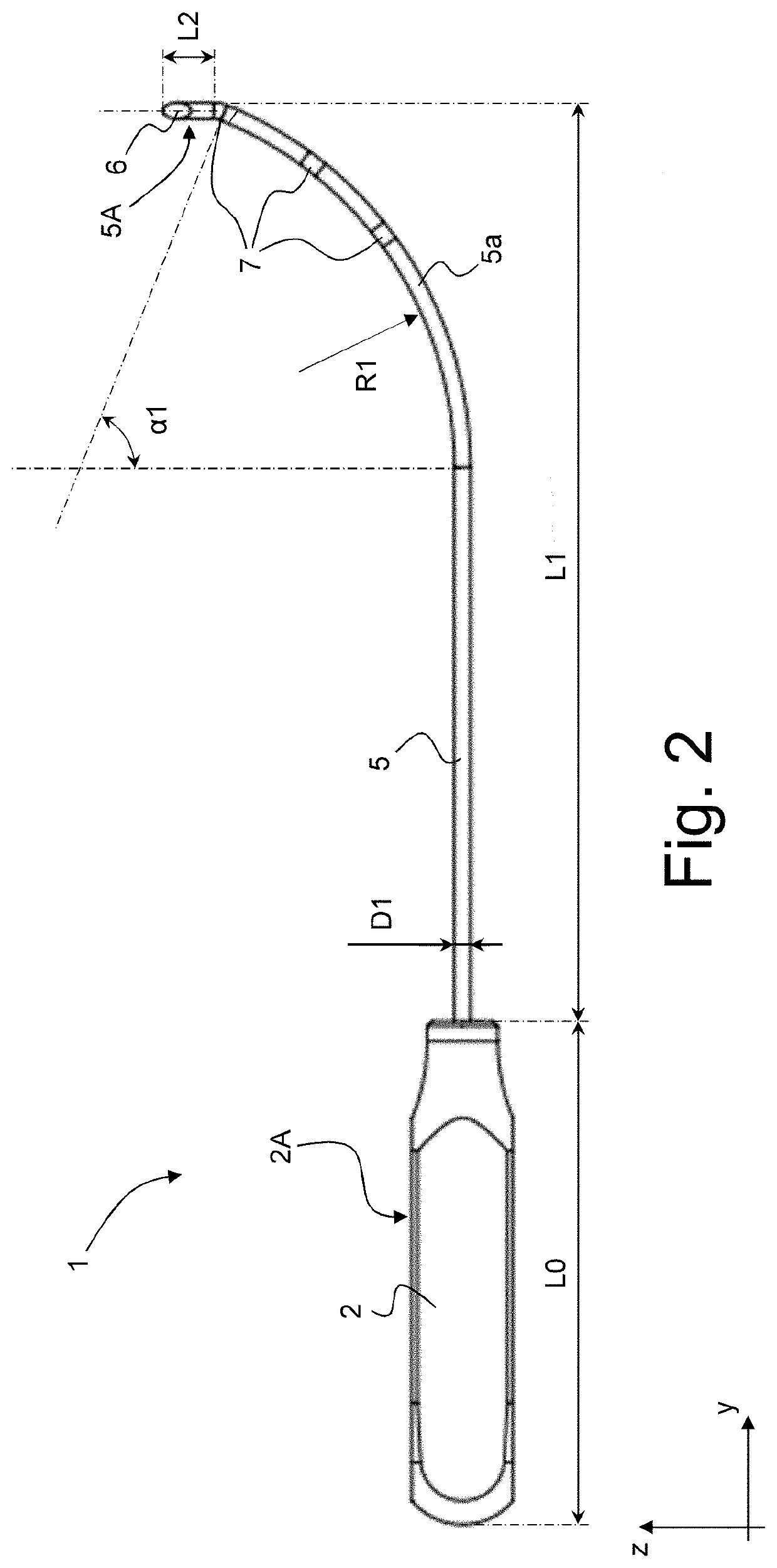
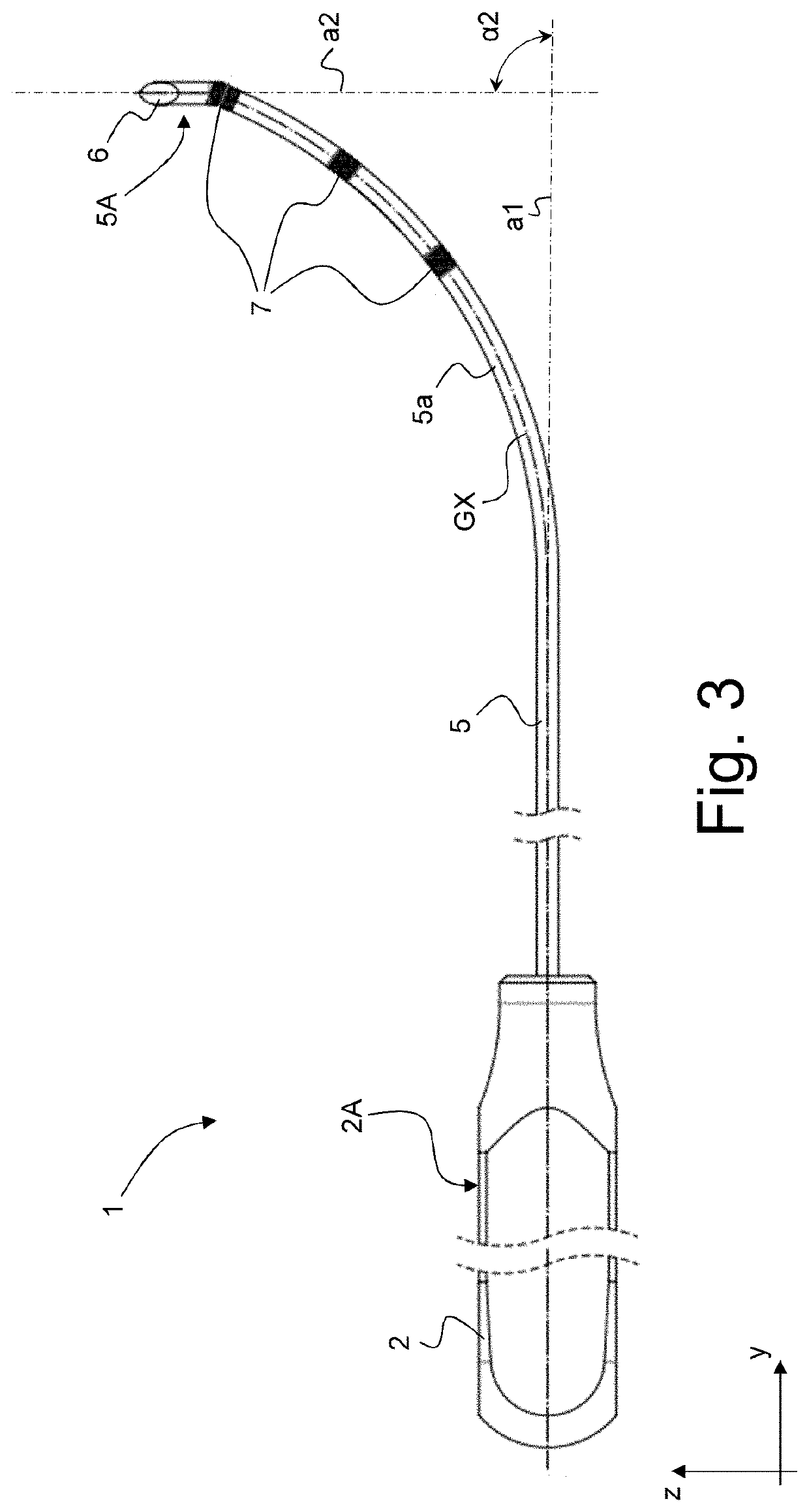
[0129]Referring more particularly to FIGS. 1 to 10, to the variant of FIGS. 23 to 27, and to the embodiment of FIGS. 32 to 37A-C, one can note that an end section of the elongated rod member 5, 5* resp. 105, at the terminal end 5A, 5A*, resp. 105A, of the second portion, extends substantially perpendicularly to the first direction a1, namely along a second direction a2 that is parallel to the z axis. In other words, angle α2 depicted in FIGS. 3, 23 and 32 is substantially 90°.

[0130]In the illustrated examples, the second portion of the elongated rod member 5, 5*, resp. 105, includes a single curved section 5a, 5a*, resp. 105a, extending over an angle α1 (see FIG. 2 which applies by analogy to the variant of FIGS. 23 to 27 and to the embodiment of FIGS. 32 to 37A-C) that exceeds 60° and a radius of curvature R1 of the curved section 5a, 5a* resp. 105a, is of the order of 30 to 45 mm. By way of illustration, angle α1 and radius of curvature R1 can be selected to equal approximately 68...


PUM


Abstract

A medical instrument for percutaneous release procedures, especially on upper or lower limbs, including percutaneous carpal tunnel release or percutaneous A1 pulley release. The medical instrument includes a handle portion to allow handling, orientation and manipulation of the medical instrument by a surgeon, and an elongated rod member secured to the handle portion and extending substantially within a defined plane. A first portion of the elongated rod member extends substantially along a first direction within the defined plane away from the handle portion, and a second portion of the elongated rod member is curved and / or bent within the defined plane. A free end of the elongated rod member, at a terminal end of the second portion, may be shaped as a beveled end including a beveled surface, which beveled end acts as a cutting device to severe tissue, and the beveled surface being inclined with respect to the defined plane.

Description

TECHNICAL FIELD[0001]The present invention generally relates to a medical instrument for percutaneous release procedures, especially percutaneous release procedures on upper or lower limbs, such as but not limited to percutaneous carpal tunnel release and percutaneous A1 pulley release. The invention is also applicable to other release procedures such as but not limited to tenolysis, tenotomy, tenotomy-lengthening, aponeurotomy, neurolysis and neurotomy.BACKGROUND OF THE INVENTION[0002]Carpal tunnel syndrome (CTS) and trigger finger syndrome (TFS) can conveniently be treated by surgical release procedures. These surgical release procedures are typically carried out using simple puncture needles or more complex hook knives or push knives. Such medical instruments may also be used for other surgical release procedures on upper or lower limbs, such as for the treatment of Morton's neuroma, tarsal tunnel release, de Quervain syndrome, epicondylalgy, shoulder surgery, and similar release...

Claims


Application Information

Patent Timeline
Patent Type & Authority Applications(United States)
IPC IPC(8): A61B17/32
CPCA61B17/320036A61B2090/3925A61B2090/08021A61B2017/00455A61B2090/3937A61B2017/00314
Inventor MOUNGONDO, FABIAN
Owner SWIBRACE SA
Learn More