Cooling apparatus for electronic devices

a technology of electronic devices and cooling apparatuses, which is applied in the direction of semiconductor devices, instruments, computing, etc., can solve the problems of limited heat dissipation space within the electronic device, difficult to discharge internal heat to the outside of the device, and limited operation temperatures of various electronic components used in the electronic devi

Inactive Publication Date: 2008-05-15
NEC CORP
View PDF22 Cites 10 Cited by
  • Summary
  • Abstract
  • Description
  • Claims
  • Application Information

AI Technical Summary

Benefits of technology

[0017]It is another object of the present invention to provide a cooling apparatus for electronic devices which is easy to build and to fix it to electronic devices, superior in thermal conduction and heat dissipation, and possible to make thin the total configuration of the apparatus.
[0041]The plurality of piezoelectric pump driving members may control timings of introduction and exhaust of the coolant of the plurality of pump members in different timing to each other.

Problems solved by technology

On the other hand, operation temperatures of various electronic components used in the electronic devices are limited in general in view of thermal reliability and temperature dependence of the operation characteristics.
However, for example, in a laptop PC and the like which is packaged in high-density with electronic components, a heat discharging space within the electronic device is limited.
Then, regarding a CPU with power consumption over 30 W, it has been difficult to sufficiently discharge the internal heat to the outside of the device, although a conventional cooling fan or a combination of the cooling fan and the heat pipe has a proper cooling performance for the CPU with power consumption around 30 W.
Accordingly, the same issue with a laptop PC in regard to the heat dissipation has been existed as well.
Then, assembly and fixing of the apparatus to an electronic device body are complex.
Furthermore, since a setting position of the air cooling unit having a fan is limited to the vicinity of the enforced cooling unit 104 in which the liquid circulation pump 106 is set, the cooling performance has been not sufficient.
In addition, since a conventional cooling apparatus is equipped with the liquid circulation pump 106 for the enforced air cooling, a pump unit has become large and complex compared with that of pump itself, thereby the total configuration of the apparatus has been thick.
Furthermore, since the conventional cooling apparatus is built with a resin gasket, the coolant of the apparatus has been lost bit by bit by leaking outside of the apparatus during long use, and thereby the cooling performance has been degraded.

Method used


Image

  • Cooling apparatus for electronic devices
  • Cooling apparatus for electronic devices
  • Cooling apparatus for electronic devices

Examples


Embodiment Construction

[0083]Embodiments of the present invention will be explained in detail by referring figures.

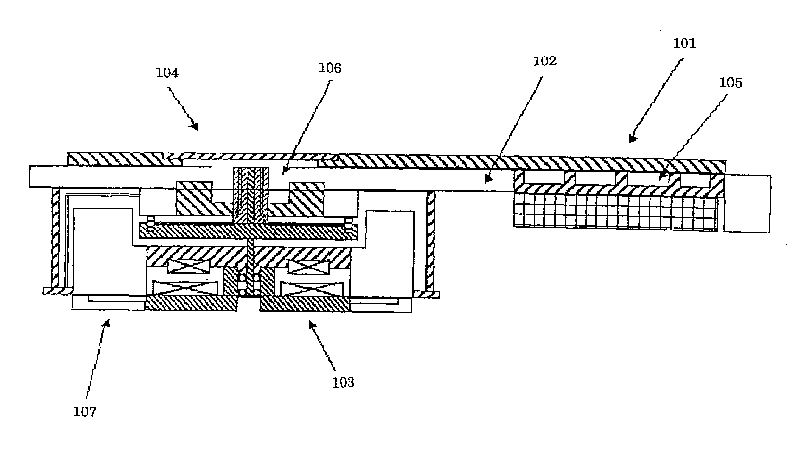
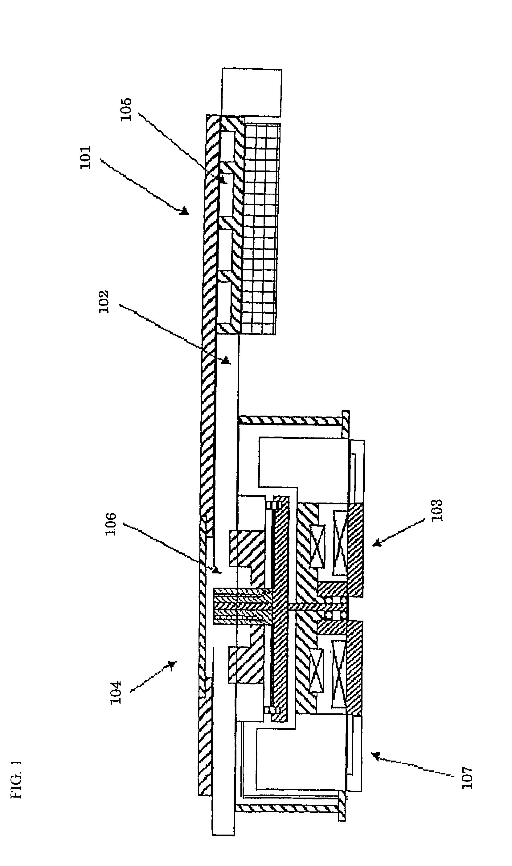
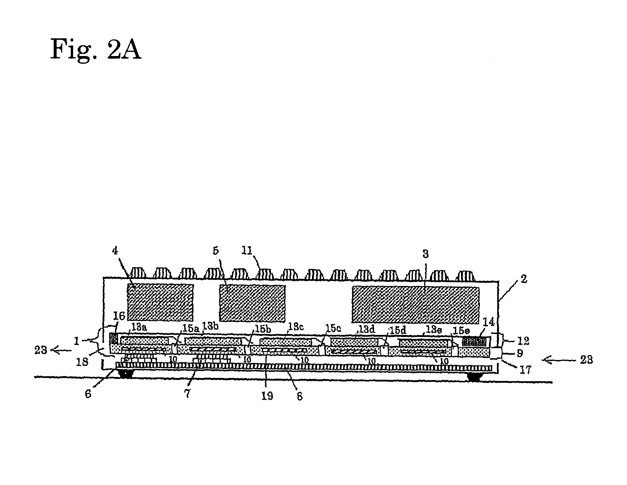
[0084]FIG. 2A is a cross sectional view showing a configuration of a cooling apparatus fixed in electronic devices in the preferred embodiment of the present invention. FIG. 2B is a perspective view looked from backside of a cooling apparatus shown in FIG. 2A. FIG. 2C is a cross sectional view cut at A-B line shown in FIG. 2B

[0085]A note type personal computer (hereinafter, referred to as note PC) is picked up for explanation as a typical electronic device for mounting a cooling apparatus for electronic devices of this embodiment. However, applications of the cooling apparatus for electronic devices of the embodiment is not limited to the note PC, but also applicable to an apparatus which generates heat by operation. In the note PC, as shown in FIG. 2A, a CD-ROM 3, PC card 4, HDD 5, a CPU 6 which locally generates heat, and a heat generator 7, for example, chip set and the like are mounted on...


PUM


Abstract

The present invention provides a cooling apparatus which is easy to build and to fix it to electronic devices, superior in thermal conduction and heat dissipation, and possible to make thin the total configuration of the apparatus. The liquid cooling unit 9 and the air cooling unit 12 are formed in a unit. A heat absorption surface 19 of the liquid cooling unit 9 is contacted or bonded to the heat generation component such as the CPU and the heat generator, which have the largest power consumption and also locally generate heat within a small area in the box 2. In the liquid cooling unit 9, a liquid cooling pump 14 composed of an electromagnetic pump is arranged for circulating the coolant in the flow path 10. The heat generated by the heat generation components such as CPU 6, heat generator 7, and the like is thermally diffused with heat conduction into the whole liquid cooling unit 9 by circulating the coolant with the liquid cooling pump 14.

Description

FIELD OF THE INVENTION[0001]The present invention relates to a cooling apparatus for electronic device, and, more particularly to the cooling apparatus for electronic device suitable for cooling a heat generation component such as a CPU and the like mounted on, for example, a laptop computer.[0002]All of patents, patent applications, patent publications, scientific articles and the like, which will hereinafter be cited or identified in the present application, will hereby be incorporated by references in their entirety in order to describe more fully the state of the art, to which the present invention pertains.DESCRIPTION OF THE RELATED ART[0003]Recently, with an increase in processing volume and processing speed, a heat generator having a large power consumption such as a CPU and the like is mounted on electronic devices such as, for example, a PC. An amount of heat generated by the heat generator is increasing linearly. On the other hand, operation temperatures of various electro...

Claims


Application Information

Patent Timeline
Patent Type & Authority Applications(United States)
IPC IPC(8): F28D15/00G06F1/20H01L23/467H01L23/473
CPCG06F1/20H01L23/467H01L23/473H01L2924/0002H01L2924/00
Inventor MIKUBO, KAZUYUKIKITAJO, SAKAESASAKI, YASUHIROOCHI, ATSUSHIYAMAMOTO, MITSURU
Owner NEC CORP
Why Eureka
Try Eureka