Coupling for optical-fiber connectors

US20090136183A1Active Publication Date: 2009-05-28COMMSCOPE TECH LLC

Image

  • Coupling for optical-fiber connectors
  • Coupling for optical-fiber connectors
  • Coupling for optical-fiber connectors

Examples


Embodiment Construction

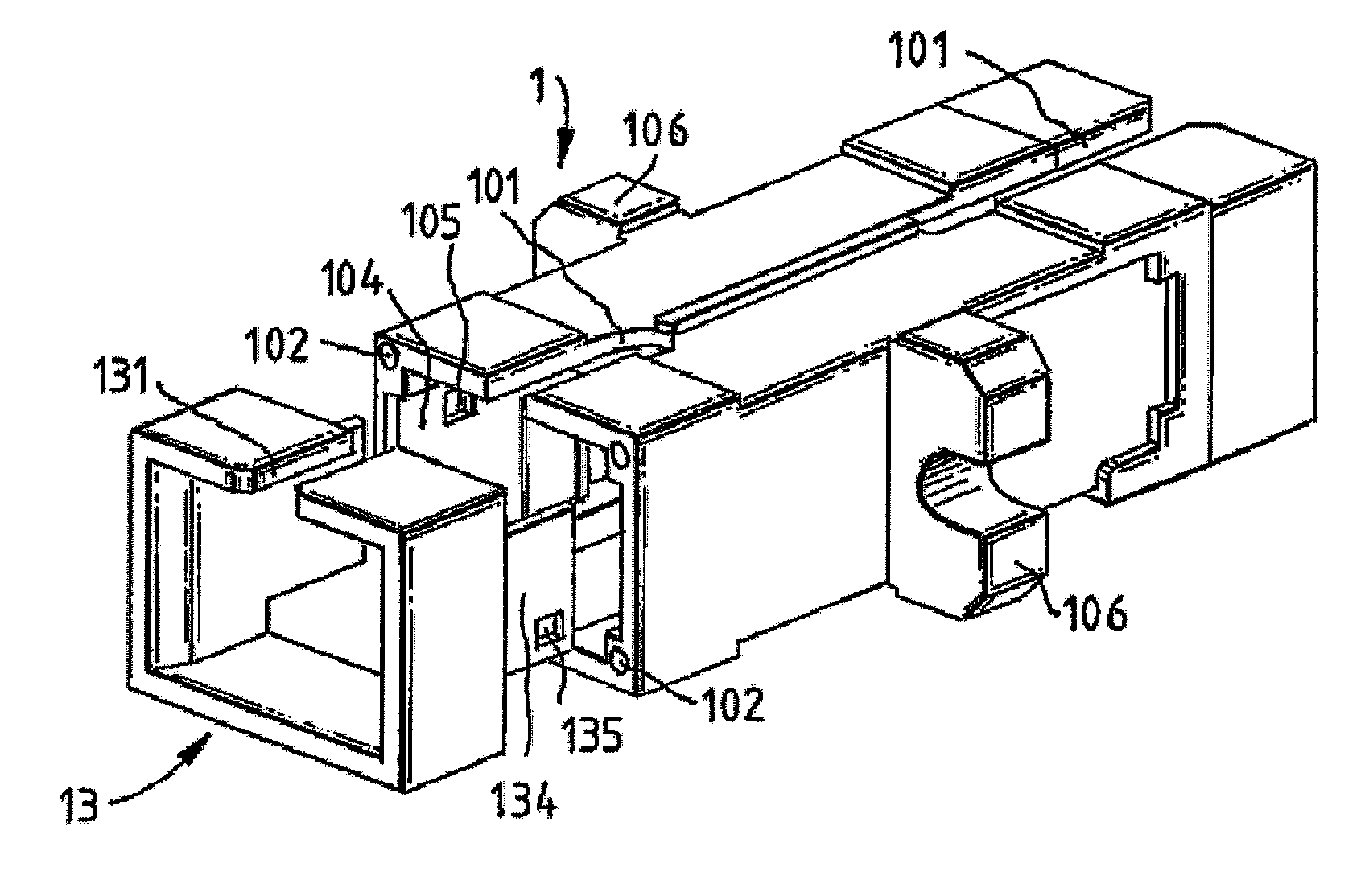
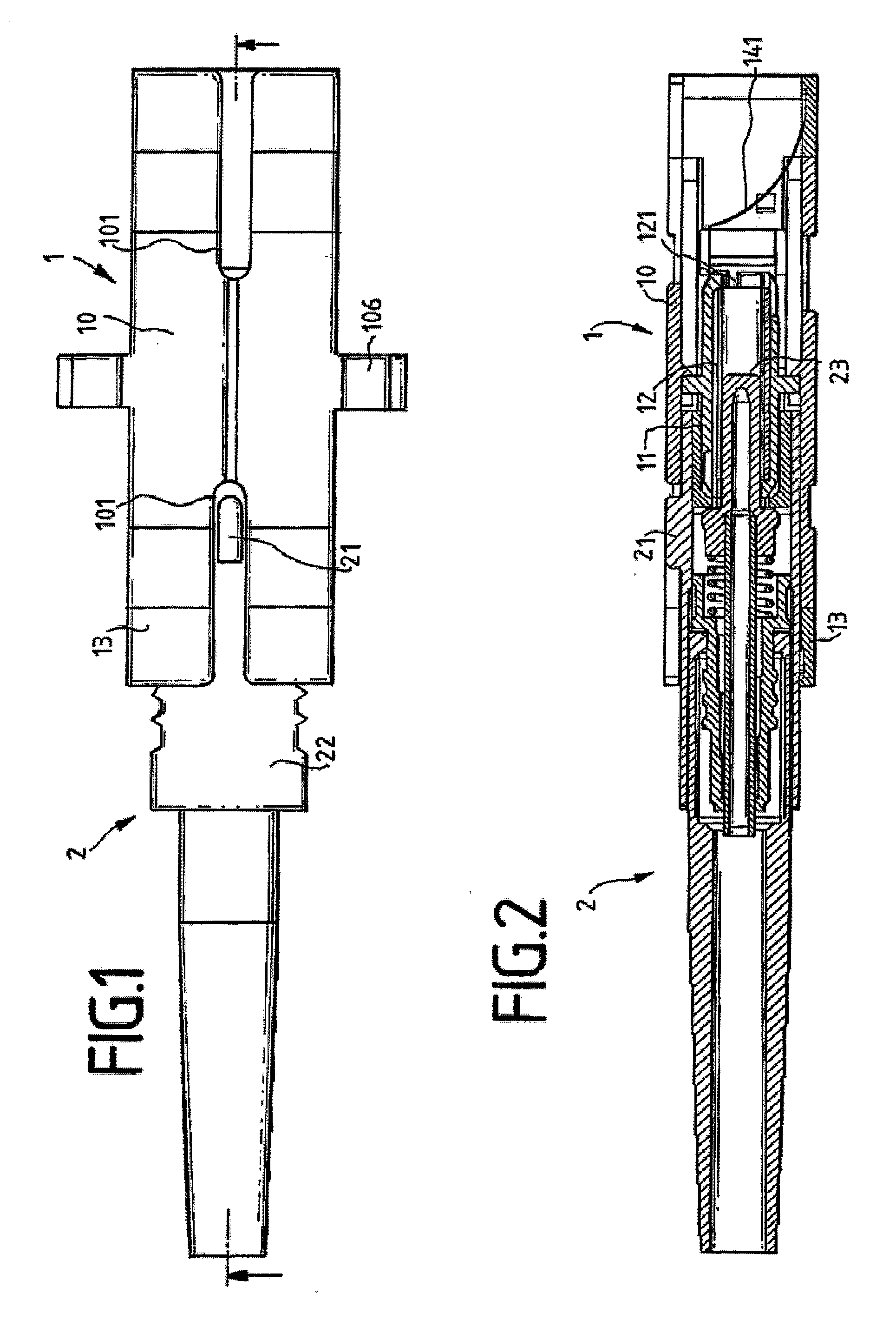
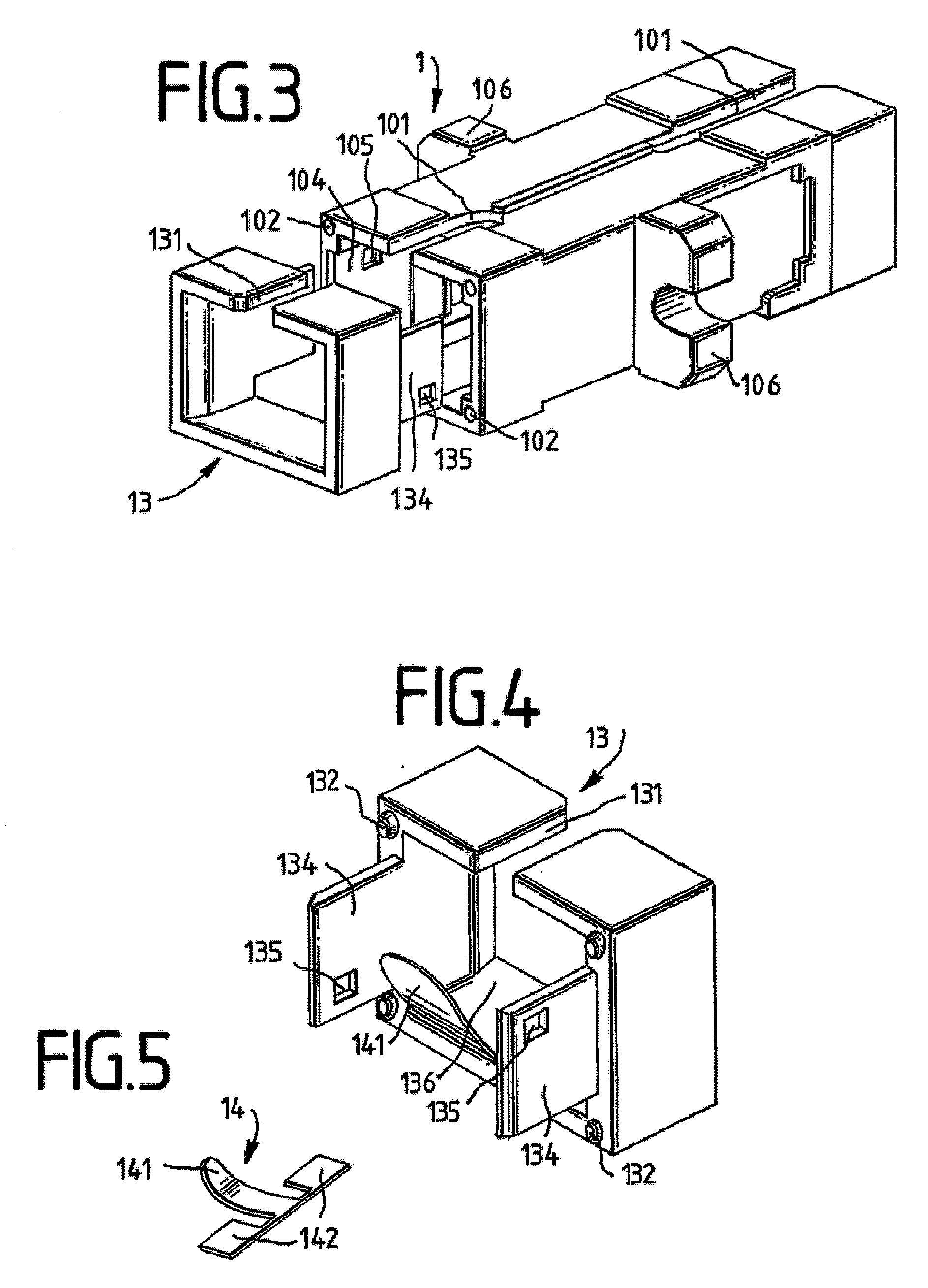
[0023]FIG. 1 shows, schematically, a coupling 1 for the coaxial connection of fiber-optic cables. The coupling comprises a coupling housing 10 into which a plug-in connector 2 can be plugged in from each end. The coupling housing 10 is designed with flanges 106, by means of which the coupling 1 can be attached to an installation opening (not illustrated). A connection piece 13 can be latched onto the coupling housing 10. The length of the connection piece 13 may be selected here such that there is no blockage of access to the grip region 22 provided on the plug-in connector 2 in the plugged-in state. The plug-in connector 2 is designed, for assisting guidance in the coupling housing 10, with a tongue 21, which can be introduced into a complementary groove 101 on the coupling housing 10 and into a groove 131 on the connection piece 13.

[0024]FIG. 2 shows a section through the coupling 1 and the plug-in connector 2. The designations here correspond to FIG. 1. A sleeve mount 11 with a s...


PUM


Abstract

A coupling (1) for receiving at least two plug-in connectors (2) which are joined to glass fiber cables, comprising at least one moveable cover (14) which is associated with a sheath opening (121), said cover covering the opening (121) of the sheath in a first position, and being able to be moved into a second position by introducing a plug-in connector (2), whereupon the cover (14) releases the opening (121) in the sheath, said cover (14) comprising a bent metallic leaf spring (141) and said leaf spring (141) being unstressed in the first position and the curvature of the leaf spring (141) being selected in such a way that a ferrule (23) of the plug-in connector (2) never comes into contact with the leaf spring (141) during the insertion process.

Description

CROSS REFERENCE TO RELATED APPLICATIONS[0001]This application is a Continuation of application Ser. No. 10 / 513,243, filed 1 Sep. 2005, which is the National Stage of Application PCT / EP03 / 04293, filed 25 Apr. 2003, which claims benefit to 102 19 892.6, filed 3 May 2002 in Germany, and which applications are incorporated herein by reference.BACKGROUND OF THE INVENTION[0002]It is known for optical fibers to be connected coaxially to plug-in connectors by means of couplings. The plug-in connectors are designed with a ferrule at the free end for the purpose of central fixing. The two ferules of the plugs which are to be connected can be introduced into a sleeve of the corresponding coupling, the ferrules coming into contact at the end surfaces. The sleeve is mounted in a sleeve mount. The outer shape of the coupling housing is defined by way of the given geometries of a known installation opening. Light waves are transmitted by fiber-optic cables. In order to prevent the emission of harm...

Claims


Application Information

Patent Timeline
28 May 2009
Publication
US20090136183A1
IPC
G02B6/38; G02B6/42
CPC
G02B6/3825; G02B6/3849; G02B6/4296; G02B6/38
Inventors
KAHLE, EBERHARD; KRAMER, ANNE