Installation for optically examining surface regions of objects

Active Publication Date: 2018-10-25
EISENMANN SE
View PDF13 Cites 1 Cited by
  • Summary
  • Abstract
  • Description
  • Claims
  • Application Information

AI Technical Summary

Benefits of technology

[0028]The embodiment is additionally achieved by way of a light-emitting system for an installation as described above having at least one first and one second light-emitting unit, wherein the first and the second light-emitting units are of identical construction. This has the advantage that the light-emitting units can be produced in cost-effective fashion and a corresponding multitude of possibilities exist within the test region for arranging an operator apparatus. The operator apparatus can also be arranged in any of the light-emitting units, if necessary. At the same time, only one type of light-emitting units needs to

Problems solved by technology

A large number of different surface defects can occur during the painting process.
However, if the accurate assessment of the surface requi

Method used


Image

  • Installation for optically examining surface regions of objects
  • Installation for optically examining surface regions of objects
  • Installation for optically examining surface regions of objects

Examples


Embodiment Construction

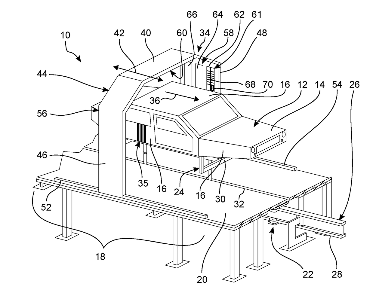
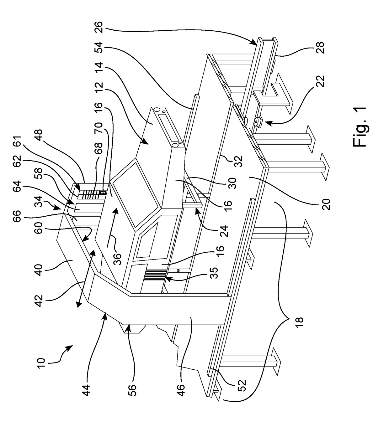
[0034]FIG. 1 shows a perspective view of an installation 10 for optically or visually examining surface regions of objects 12. In the present case, vehicle bodies 14 are shown as examples of objects 12. The object 12 shown in FIG. 1 has surface regions 16 to be examined, some of which are provided with a corresponding reference sign. During a test operation, the entire surface of the object 12 is tested by way of an inspector successively checking individual surface regions 16.

[0035]In the exemplary embodiment of the installation 10, shown in FIG. 1, the quality of the paint of vehicle bodies 14 is visually inspected by an inspector. To this end, a test zone 18 having a platform 20 on which an inspector may walk is provided in the installation 10. The vehicle bodies 14 are transported into the test zone 18 using a transport system 22.

[0036]In the present exemplary embodiment, the transport system 22 comprises a multiplicity of transport carriages 24, on which the vehicle bodies 14 a...


PUM


Abstract

In various examples, an installation is provided for optically examining surface regions of objects, in particular of painted vehicle bodies, having a test light apparatus for irradiating an object, which is situated in a test region of the installation, with test light and/or for producing a test pattern on the surface region, wherein the test light apparatus has a light-emitting system having a plurality of light-emitting units for emitting test light into the test region, wherein the light-emitting units have a transparent cover with respect to the test region. An operator apparatus is arranged, as viewed from the test region, behind the transparent cover and is set up such that the operator apparatus can be operated by touching at least one section of the cover or/and by approaching such a section. A light-emitting system for such an installation and to a test light module for assembling such an installation are provided.

Description

CROSS-REFERENCE TO RELATED APPLICATIONS[0001]This application claims priority to and the benefit of German Patent Application No. 10 2017 108 770.2 filed Apr. 25, 2017 which is hereby incorporated by reference in its entirety.BACKGROUND OF THE INVENTION1. Field of the Invention[0002]The invention relates to an installation for optically examining surface regions of objects, in particular of painted vehicle bodies.2. Description of the Prior Art[0003]In installations of this type, in particular the surfaces of painted vehicle bodies are visually examined by inspectors in respect of quality. Defects in the surface result in local distortions of a test pattern that is projected onto the vehicle body as compared to a projection of the same test pattern onto a surface that is ideally free from defects. In this way, an experienced inspector will quickly notice any surface defects that are present and can mark them in a suitable fashion.[0004]A large number of different surface defects can...

Claims


Application Information

Patent Timeline
IPC IPC(8): G01N21/88G01N21/89
CPCG01N21/8806G01N21/8803G01N21/8914G01M11/081G01M17/007G01N21/9515
Inventor ROCKLE, JURGEN
Owner EISENMANN SE
Why Eureka
Try Eureka