
Localisation device for visually determining the location of a vehicle

A technology for determining devices and vehicles, applied in image analysis, image enhancement, instruments, etc., can solve problems such as high cost and complex maps

Pending Publication Date: 2021-04-09
CONTINENTAL AUTOMOTIVE GMBH
View PDF0 Cites 1 Cited by
  • Summary
  • Abstract
  • Description
  • Claims
  • Application Information

AI Technical Summary

Problems solved by technology

Building such maps through conventional methods of surveying technology is complex and costly
Furthermore, position determination or exact positioning in these maps presents a great challenge, since automatic vehicle control can only be implemented with exact position determination within the map, e.g. for correct lane selection

Method used


Image

  • Localisation device for visually determining the location of a vehicle
  • Localisation device for visually determining the location of a vehicle
  • Localisation device for visually determining the location of a vehicle

Examples


Embodiment Construction

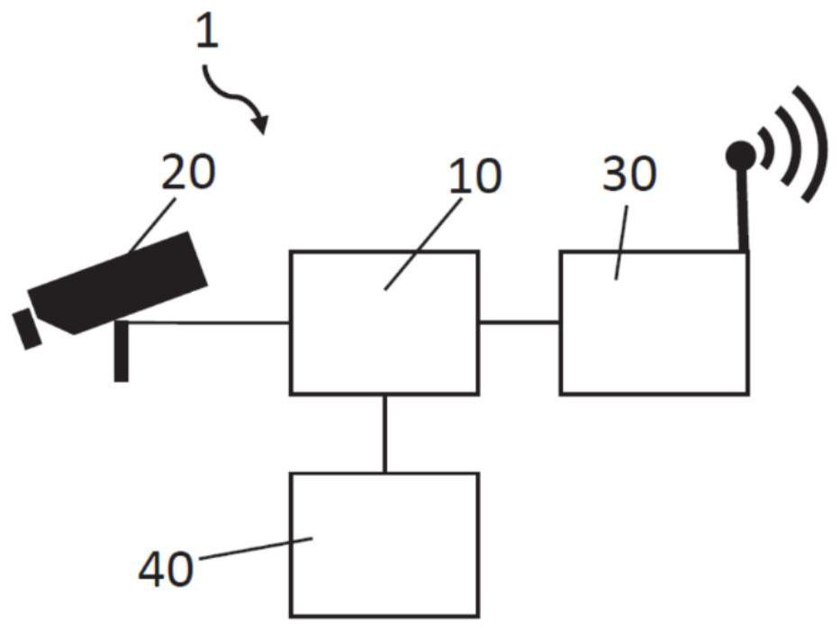
[0052] figure 1 A position determination device 1 with a control unit 10 and a camera unit 20 is shown. Furthermore, the position determination device 1 can optionally have a transmitter / receiver unit 30 and a locating unit 40 . In this case, camera unit 20 detects image data of the vehicle surroundings. This image data can be evaluated by the control unit 10 in order to recognize landmarks therein, i.e. to recognize unique objects, unique object components or components of the surrounding environment, such as street lights, traffic signs, traffic lights, buildings, curbs , power boxes, fire hydrants, road signs, parking meters, walls, billboards or sculptures and other components. Furthermore, the control unit 10 may also determine for each recognized landmark a quality value corresponding to the recognizability or visibility, stability and / or contribution to the position determination of the corresponding landmark. The higher the quality value, the more identifiable and s...


PUM


Abstract

The invention relates to a localisation device (1) for visually determining the location of a vehicle (3). The localisation device has a camera unit (20) for capturing image data (11), and a control unit (10). The control unit (10) is designed to recognise one or more landmarks (15a) in the captured image date (11). The control unit (10) is further designed to determine a quality value for each recognised landmark (13a, 13b), which quality value corresponds to the recognisability, the permanence and / or the contribution of the landmark (13a, 13b) to the localisation, wherein the determination of the quality value involves a plurality of recognitions of the particular landmark (13a, 13b). A plurality of quality values for one landmark can also be determined for different observation positions or observation directions. Furthermore, the control unit (10) is designed to adjust the quality value of a landmark (13a, 13b) already contained in a map, based on a new recognition by the localisation device (1). The control unit (10) is designed to determine the position of the localisation device (1) on the basis of the recognised landmarks (13a, 13b) in conjunction with the map. The control unit (10) is further designed, in conjunction with a positioning unit (40), to determine the position of landmarks (13a, 13b) in relation to a global coordinate system.

Description

technical field [0001] The invention relates to a position determination device for visual position determination of a vehicle, a backend for generating a map for visual position determination, a vehicle with such a position determination device, a method for visual position determination, a computer program element and computer readable storage media. Background technique [0002] The development of driver assistance systems up to automated driving has received increasing attention over the years. A core component of such systems is accurate perception of their surroundings. This also includes awareness of other traffic participants, infrastructure and lane orientation. In addition to processing sensor-based signals directly in the vehicle, an accurate digital map is absolutely essential for the navigation of autonomous systems. Building such maps through conventional methods of surveying technology is complex and costly. Furthermore, the position determination or exact...

Claims


Application Information

Patent Timeline
Patent Type & Authority Applications(China)
IPC IPC(8): G01C21/28
CPCG01C21/28G06T7/73G06V20/56G01C21/30G06T2207/30252
Inventor S·卢特哈特V·威尔特B·拉特克
Owner CONTINENTAL AUTOMOTIVE GMBH
Learn More