
A device for transporting surgical instruments

Active Publication Date: 2021-10-29
广州富玛医药科技股份有限公司
View PDF3 Cites 0 Cited by
  • Summary
  • Abstract
  • Description
  • Claims
  • Application Information

AI Technical Summary

Problems solved by technology

The construction waste transportation equipment can realize the concentrated transportation of waste on higher building floors, reduce the number of times of manual handling of waste, reduce the work intensity of the staff, and speed up the efficiency of waste cleaning", but it cannot The fixed area of ​​the device is adjusted, which affects the fixing effect of the device;
[0006] 3. The comparative document CN108382892A discloses a stable transport equipment for cement tubular parts, "comprising a high-level transport device for transporting the pipe, the high-position transport device is fixed on the transport carriage by fasteners, and the high-position The delivery device includes a placement plate for placing pipe fittings, and a guide connecting rod for connecting the pulling device. The guide connecting rod is vertically arranged on the placing board; the pulling device is arranged on the guide connecting rod, and the The pulling device includes a connector and a pull cord arranged on the guide connecting rod, and the two connectors are respectively arranged on the guide connecting rods parallel to each other. In between, the two ends of the pull cord are respectively connected to the connector, the transmission device is arranged on the pull cord, the connector is a sliding sleeve, and the guide connecting rod and the connector form a sliding guide fit", but for the device The internal garbage lacks a corresponding storage and storage structure, which increases the difficulty of garbage disposal

Method used


Image

  • A device for transporting surgical instruments
  • A device for transporting surgical instruments
  • A device for transporting surgical instruments

Examples


Embodiment Construction

[0035] The following will clearly and completely describe the technical solutions in the embodiments of the present invention with reference to the accompanying drawings in the embodiments of the present invention. Obviously, the described embodiments are only some, not all, embodiments of the present invention. Based on the embodiments of the present invention, all other embodiments obtained by persons of ordinary skill in the art without making creative efforts belong to the protection scope of the present invention.

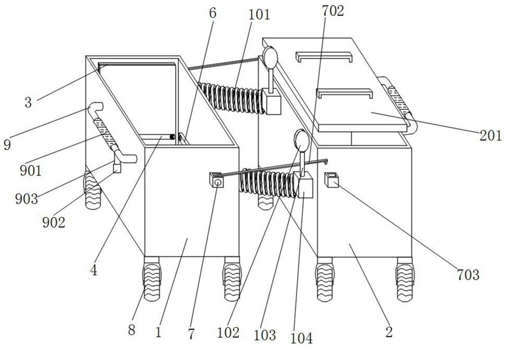
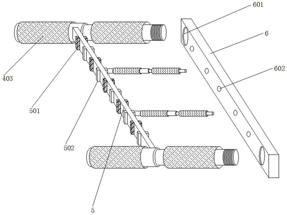
[0036] see Figure 1-8 , an embodiment provided by the present invention: a surgical instrument delivery device, including an appliance cabinet 1, a garbage cabinet 2, a back panel 3, a long rod 4, a clamping plate 5 and a handrail 9, and one side of the appliance cabinet 1 There are two sets of connecting springs 101 fixed, the appliance cabinet 1 can be used to place the instruments needed for surgery, and the setting of the connecting springs 101 allows the...


PUM


Abstract

The invention discloses a device for transporting surgical instruments, which comprises an appliance cabinet, a garbage cabinet, a back panel, a long rod, a clamping plate and a handrail. Two sets of connecting springs are fixed on one side of the appliance cabinet, and the connecting springs An installation base is fixed at one end of the installation base, a garbage cabinet is fixed on one side surface of the installation base, a back panel is welded on the back inner wall and the front inner wall of the appliance cabinet, and a long rod is welded on one side inner wall of the appliance cabinet, so A clamping plate is installed on the surface of the long rod through a fitting block, a fixing plate is welded on the inner wall of the other side of the appliance cabinet, and a fixing groove is welded on the front of the appliance cabinet. The present invention is provided with an appliance cabinet, and when the device is transported in curves, corners and other blind spots, the convex mirror can be used to check the road conditions, and then the connecting spring is used to realize the step-by-step turning of the device, so as to avoid the excessive length of the device. The situation that makes turning difficult occurs for a long time, which facilitates the turning and transportation of the device.

Description

technical field [0001] The invention relates to the field of trolleys specially suitable for surgical or diagnostic equipment or instruments, in particular to a transporting equipment for surgical instruments. Background technique [0002] With the advancement of medical technology, more and more diseases have been conquered. The necrotic tissue and lesions in the patient's body can be removed through surgery, and the damaged tissue in the patient's body can also be replaced and maintained, thus greatly improving the cure of the disease. Possibly, but with the refinement of the operation content, the types of surgical instruments are gradually diversified. Some surgical instruments that require special storage and management need to be sent back to the designated storage place for special storage after the operation is completed. Save to ensure its subsequent normal use. [0003] The defectives that exist in existing surgical instrument delivery equipment are: [0004] 1. ...

Claims


Application Information

Patent Timeline
Patent Type & Authority Patents(China)
IPC IPC(8): A61B50/30
CPCA61B50/30
Inventor 魏燕丹
Owner 广州富玛医药科技股份有限公司
Learn More