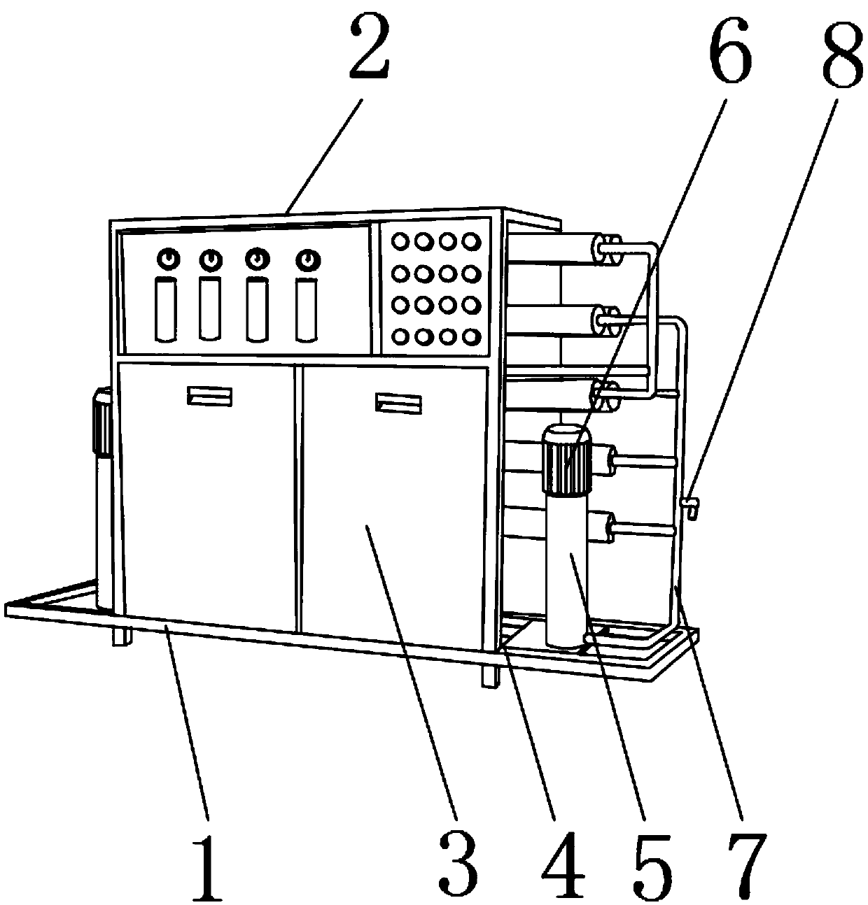
Extraction device for soybean protein concentrate
A soybean protein concentrate and extraction device technology, which is applied in the field of soybean protein concentrate extraction devices, can solve the problems of waste of resources, danger, and inconvenient observation of pipelines interlaced, and achieves the effect of easy repair
- Summary
- Abstract
- Description
- Claims
- Application Information
AI Technical Summary
Problems solved by technology
Method used
Image
Examples
Embodiment 1
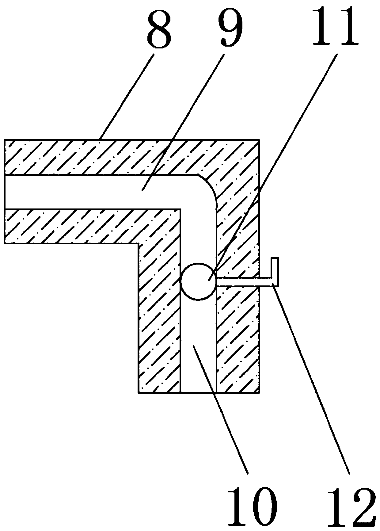
[0027] refer to figure 2 , the outer surface of the transport pipe 7 is welded with a sampling tube 8, and the inside of the sampling tube 8 is provided with a shunt 9, and the inside of the sampling tube 8 is provided with a sampling tank 10 near the bottom position, and the inner surface of the sampling tank 10 is movable. The ball valve 11 is provided with a rotating rod 12 at a position close to the ball valve 11 inside the sampling tube 8 .
[0028] refer to figure 2 The inside of the ball valve 11 is provided with a through hole, and a weld is provided between the ball valve 11 and the rotating rod 12. The rotation of the rod 12 can adjust the size of the water flow during sampling.
[0029] By welding the sampling tube 8 on the outer surface of the transport tube 7, and installing a manually rotatable ball valve 11 inside the sampling tube 8, when it is necessary to sample the material inside the transport tube 7, you only need to manually rotate the rotating rod 12...
Embodiment 2
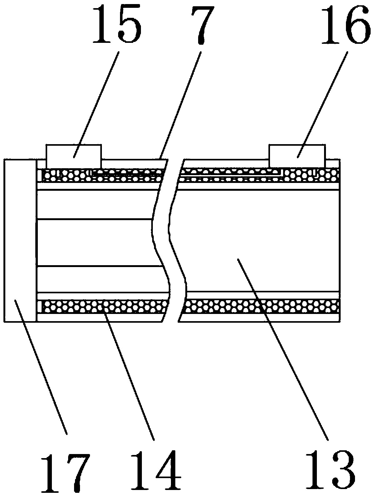
[0031] refer to image 3 The inner center of the transportation pipe 7 is provided with a conduction groove 13, and a sponge tube 14 is provided between the transportation pipe 7 and the conduction groove 13, and a storage battery 15 is welded on the outer surface of the transportation pipe 7 near one side. The outer surface of 7 is welded with a buzzer 16 away from the battery 15 .
[0032] refer to image 3 The top outer surface of the storage battery 15 is provided with a power interface, and the bottom outer surface of the storage battery 15 is provided with a positive pole and a negative pole, the negative pole is located on one side of the positive pole, and the bottom outer surface of the buzzer 16 is provided with a positive lead. pin and the negative pin, the positive pin is located on one side of the negative pin, and a lead is provided between the positive post and the positive pin. When the sponge tube 14 enters water, the current flows out through the positive po...
Embodiment 3
[0035] refer to Figure 4 , the transportation tube 7 is welded with a connecting ring 17 near the side of the storage battery 15, and the outer surface of one side of the connecting ring 17 is welded with a sealing ring 18, and the inner center of the sealing ring 18 is provided with an inner wall 19, and the inner surface of the inner wall 19 is welded There are a plurality of connecting plates 20, and the inside of the connecting plates 20 is welded with a support rod 21, and the outer surface of the front end of the support rod 21 is fixed with an ultrasonic generator 22 by bolts.
[0036] refer to Figure 4 , the outer surface of the connecting ring 17 is provided with a positive pole interface and a negative pole interface, and the positive pole interface is located on one side of the negative pole interface.
[0037] By installing the sonotrode 22 inside the transport pipe 7, inserting the positive pole of the external power supply into the positive pole groove, and in...
PUM
 Abstract
Description
Claims
Application Information
 - R&D
- Intellectual Property
- Life Sciences
- Materials
- Tech Scout
- Unparalleled Data Quality
- Higher Quality Content
- 60% Fewer Hallucinations
Browse by: Latest US Patents, China's latest patents, Technical Efficacy Thesaurus, Application Domain, Technology Topic, Popular Technical Reports.
© 2025 PatSnap. All rights reserved.Legal|Privacy policy|Modern Slavery Act Transparency Statement|Sitemap|About US| Contact US: help@patsnap.com


