Vacuum pipe end reducing tool

A vacuum tube and diameter reduction technology, which is used in manufacturing tools, glass remolding, glass manufacturing equipment, etc., can solve the problems of time-consuming, labor-intensive, and low efficiency, and achieve the effect of improving diameter reduction efficiency, convenient replacement, and saving reduction time.

Pending Publication Date: 2021-04-13
ANHUI ZHONGDING HOSE PROD
View PDF0 Cites 0 Cited by
  • Summary
  • Abstract
  • Description
  • Claims
  • Application Information

AI Technical Summary

Problems solved by technology

[0003] The existing work of reducing the diameter of the end of the vacuum tube is often done manually, which is time-consuming and labor-intensive, and the vacuum tube needs to be pushed in and disassembled manually, so the efficiency is low

Method used


Image

  • Vacuum pipe end reducing tool
  • Vacuum pipe end reducing tool
  • Vacuum pipe end reducing tool

Examples


Embodiment Construction

[0026] The following will clearly and completely describe the technical solutions in the embodiments of the present invention with reference to the accompanying drawings in the embodiments of the present invention. Obviously, the described embodiments are only some, not all, embodiments of the present invention. Based on the embodiments of the present invention, all other embodiments obtained by persons of ordinary skill in the art without making creative efforts belong to the protection scope of the present invention.

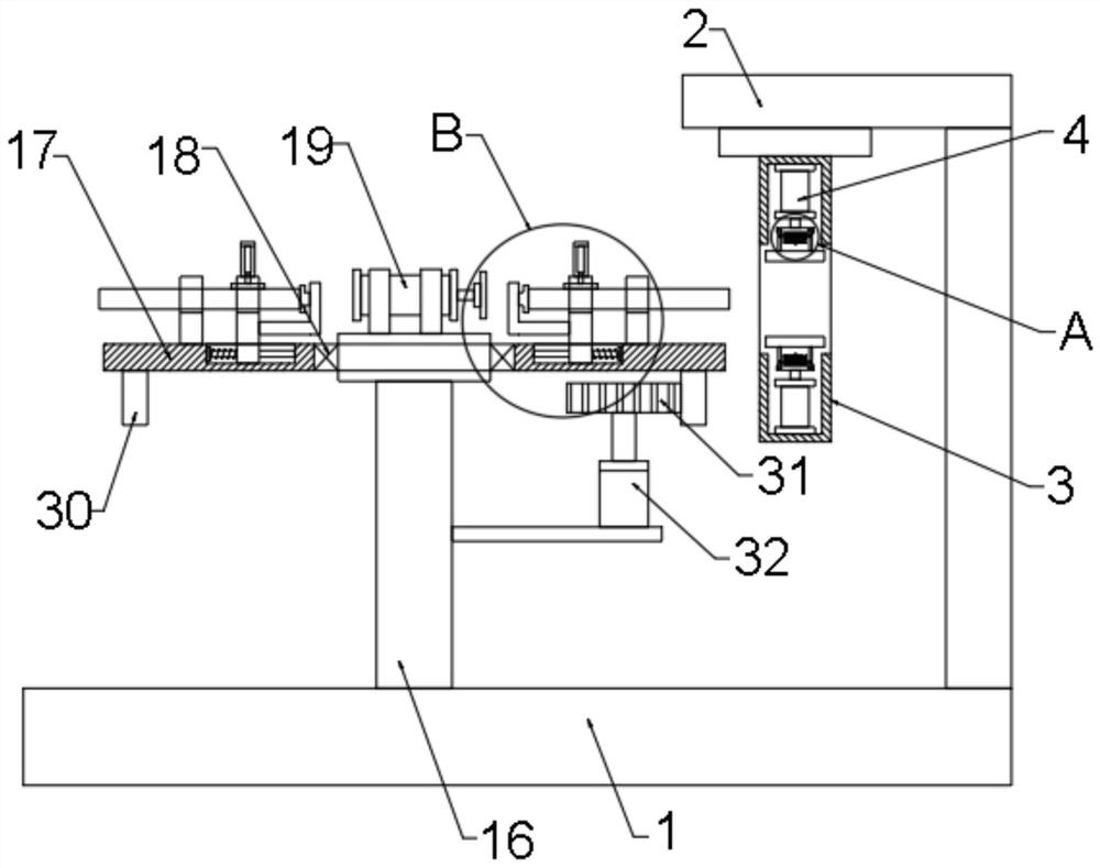
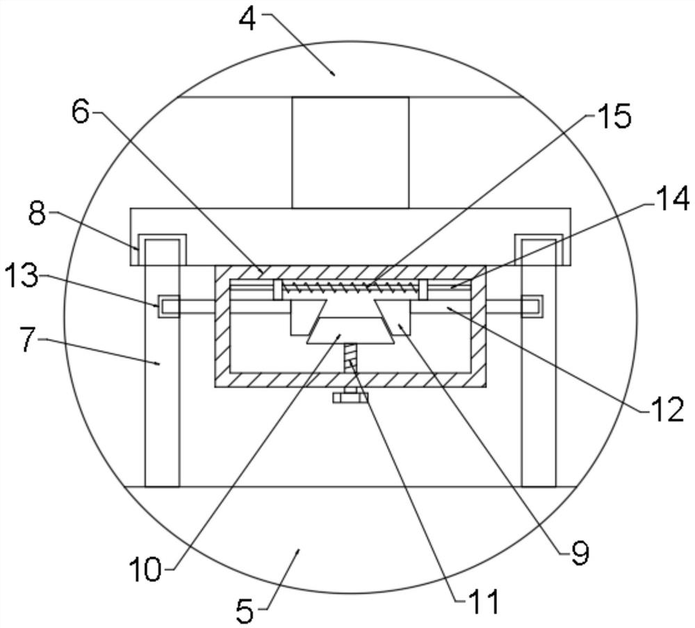
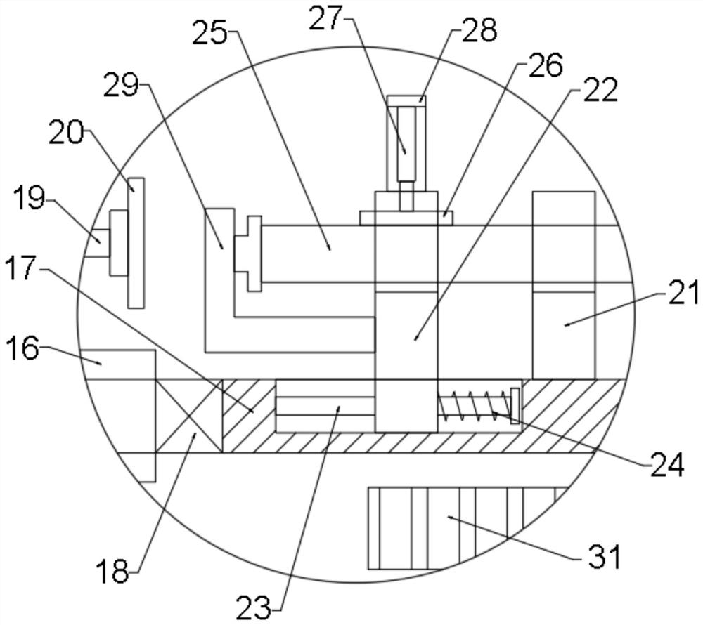
[0027] see Figure 1~6 , in an embodiment of the present invention, a vacuum tube end diameter reducing tool, including a base 1, a support frame 2 and a diameter reducing mechanism 3, the upper end of the base 1 is provided with a support frame 2, and the lower end of the support frame 2 is provided with a diameter reducing mechanism 3 , the upper and lower sides of the diameter reducing mechanism 3 are provided with hydraulic cylinders 4, and the ends of the...


PUM


Abstract

The invention discloses a vacuum pipe end reducing tool. The vacuum pipe end reducing tool comprises a base, a supporting frame and a reducing mechanism, the supporting frame is arranged at the upper end of the base, the reducing mechanism is arranged at the lower end of the supporting frame, hydraulic cylinders are arranged on the upper side and the lower side in the reducing mechanism, connecting plates are arranged at the ends, close to each other, of the hydraulic cylinders, and reducing plates are arranged on the sides, close to each other, of the connecting plates. A circular plate is arranged at the upper end of the base, a rotating plate is arranged outside the circular plate, a bearing is arranged at the joint of the rotating plate and the circular plate, an air cylinder is arranged at the upper end of the circular plate, and a second push plate is arranged at the right end of the air cylinder. When the vacuum pipe end reducing tool is used, an access door is opened, a screw rod is rotated to drive a push plate I to move downwards, and under the action of a spring, movable rods II and movable rods I on the two sides are pushed to get close to each other, so that the movable rods I are moved out of limiting grooves, the reducing plate is conveniently detached from the hydraulic cylinder, and the reducing plate is conveniently replaced; and the vacuum pipe end reducing tool is suitable for reducing the end openings of different types of vacuum pipes.

Description

technical field [0001] The invention relates to the technical field of vacuum tube processing, in particular to a vacuum tube end diameter reducing tool. Background technique [0002] "Vacuum tube" means that the inside of the glass bottle is evacuated to facilitate the flow of free electrons and effectively reduce the oxidation loss of the filament. Vacuum tubes are widely used in every corner of life. The triode is the most basic vacuum tube. Diodes, triodes, and pentodes literally represent the number of basic "poles" inside the vacuum tube. The vacuum tube has three basic poles, the first is the "cathode" (Cathode, represented by K): the cathode is of course negative, it is the place where the electron flow is released, it can be a metal plate or the filament itself, when When the filament heats the metal plate, the electrons are released and dispersed in the small vacuum glass vial. The second pole is "Plate" (Plate, represented by P), which is basically the outermo...

Claims


Application Information

Patent Timeline
Patent Type & Authority Applications(China)
IPC IPC(8): C03B23/09C03B23/045
CPCC03B23/045C03B23/092
Inventor 刘鎏陈涛杨肇兵
Owner ANHUI ZHONGDING HOSE PROD
Why Eureka
Try Eureka