Flux cored wire forming machine

A technology of flux-cored welding wire and forming machine, which is applied in the direction of wire drawing dies, etc., can solve the problems of wearing the surface of flux-cored welding wire, increasing the resistance of diameter reduction, etc., and achieves the effect of saving finishing drawing, eliminating sliding friction and reducing dust pollution.

Active Publication Date: 2016-04-13
TIANJIN SAINTEAGLE WELDING CO LTD
View PDF12 Cites 0 Cited by
  • Summary
  • Abstract
  • Description
  • Claims
  • Application Information

AI Technical Summary

Problems solved by technology

[0005] 2. Two-roll rolling cannot form a completely closed space, and there will be a gap between the upper roll and the lower roll (left and right rolls) on the side of the rolling groove. This gap is shown in the accompanying drawing of CN202290813U It can be clearly seen that the deformation of the flux-cored wire during diameter reduction may leave a space for outward flow and extension, forming two ears on the cross section (such as figure 2 shown)
This causes relative friction between the part of the flux-cored wire and the part of the roller, which increases the resistance of diameter reduction on the one hand, and wears the surface of the flux-cored wire on the other hand.

Method used


Image

  • Flux cored wire forming machine
  • Flux cored wire forming machine
  • Flux cored wire forming machine

Examples


Embodiment 1

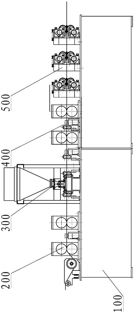
[0052] Such as image 3 with Figure 4 As shown, a flux-cored welding wire forming machine includes a base 100, on which a forming rolling stand 200, a powder feeder 300, a closing rolling stand 400 and a diameter reducing device are sequentially arranged from upstream to downstream. In this embodiment, Described reducing device is 3 active roll molds 500, and described active roll mold comprises at least one pair of passive rolls, and the axis of rotation of every pair of passive rolls is parallel to each other, also includes at least one pair of active rolls, and the rotation of every pair of active rolls The axes are parallel to each other, at least one active roll in each pair of active rolls is connected to the driving device through the transmission device or directly connected to the driving device, the rotation axes of all the active rolls and the passive rolls are in the same plane, and the plane is perpendicular to the flux cored wire . image 3 The figure only sho...

Embodiment 2

[0054] Such as Figure 5 with Image 6 As shown, a flux-cored welding wire forming machine includes a base 100, on which a forming rolling stand 200, a powder feeder 300, a closing rolling stand 400 and a diameter reducing device are sequentially arranged from upstream to downstream. In this embodiment, The diameter reducing device is a set of active roll dies 500, a set of passive roll dies 600 and a set of active roll dies arranged in sequence. The active roll dies include at least one pair of passive rolls, and the axes of rotation of each pair of passive rolls are parallel to each other. , also includes at least one pair of driving rolls, the rotation axes of each pair of driving rolls are parallel to each other, at least one driving roll in each pair of driving rolls is connected to the driving device through a transmission device or directly connected to the driving device, all the driving rolls and passive rolls The axis of rotation is in the same plane, and the plane ...

Embodiment 3

[0059] see Figure 7 to Figure 10 ,

[0060] A driving roll mold, comprising at least one pair of passive rolls, the rotation axes of each pair of passive rolls are parallel to each other, and at least one pair of driving rolls, the rotation axes of each pair of driving rolls are parallel to each other, at least one of each pair of driving rolls The driving rolls are connected to the driving device through the transmission device or directly connected to the driving device, and the rotation axes of all the driving rolls and the passive rolls are in the same plane, and the plane is perpendicular to the flux cored wire.

[0061] Specifically:

[0062] The driving roll 2 is installed on the roll shaft 24 through the rolling bearing 8, and the roll shaft is installed on the driving roll frame 11, and the driving roll frame is also provided with a driving gear shaft 1, and the driving gear shaft is installed on the driving roll bracket through the rolling bearing. A single-input ...


PUM


Abstract

The invention relates to a flux-cored wire forming machine. The flux-cored wire forming machine comprises a base, wherein the base is provided with a forming rolling frame, a powder feeder, a closed rolling frame and a reducing device in sequence from upstream to downstream; the reducing device comprises at least one driving roller die; each driving roller die comprises at least one pair of driven rolling rollers; the rotary axes of each pair of driven rolling rollers are parallel. The driving roller die also comprises at least one pair of driving rolling rollers; the rotary axes of each pair of driving rolling rollers are parallel; at least one driving rolling roller in each pair of driving rolling rollers is connected with a driving device by a transmission device or is directly connected with the driving device; the rotary axes of all the driving rolling rollers and driven rolling rollers are positioned in the same plane, and the plane is vertical to a flux-cored wire. The flux-cored wire forming machine has the advantage that the reducing efficiency is high.

Description

technical field [0001] This patent belongs to the technical field of manufacturing welding materials, which belongs to the IPC classification number B23k35 / 40, and also belongs to the technical field of forming tools for metal drawing with sections defined by rollers, balls or similar parts, and belongs to the IPC classification number B21C3 / 08 , especially relates to a flux cored wire forming machine. Background technique [0002] At present, the method of drawing to reduce the diameter of flux-cored welding wire is a main link in the production of flux-cored welding wire. Multi-turn flux-cored wire is wound on the reel to form frictional self-locking. The friction between the flux-cored wire and the reel is achieved by overcoming the reduction resistance when passing through the wire-drawing die and the friction between the wire-drawing die. . In this method, since the material of the flux-cored wire cannot be guaranteed to be completely uniform during the wire drawing p...

Claims


Application Information

Patent Timeline
Patent Type & Authority Patents(China)
IPC IPC(8): B21C3/08
CPCB21C3/08
Inventor 张国良李雪静金立鸿
Owner TIANJIN SAINTEAGLE WELDING CO LTD
Why Eureka
Try Eureka