Method and apparatus for a clog resistant orifice

a technology of orifice and orifice, which is applied in the field of medical devices, systems and methods, can solve the problems of frequent clogging limited orifice size of many medical devices, and subsequent malfunction of devices, so as to reduce the ability of clogging, eliminate tension and compression forces, and minimize the occurrence of clogging

Inactive Publication Date: 2015-03-26
HOSPI CORP
View PDF6 Cites 20 Cited by
  • Summary
  • Abstract
  • Description
  • Claims
  • Application Information

AI Technical Summary

Benefits of technology

[0007]Devices, apparatuses, systems, and methods are provided for a clog resistant orifice which exploits both the physics of the forces acting within a clogged orifice and the surrounding tube structure. The non-clogging or clog resistant orifices or holes according to the present disclosure minimize the occurrence of clogging and reduce the ability of clogs to block an orifice by one or more of the following: (i) eliminating tension and compression forces from forming within the hole, (ii) allowing the inner hole diameter to expand, which (a) can i

Problems solved by technology

Many tubes used such purposes clog frequently.
Body secretions, bacterial biofilm, or accumulating residue can tend to build up around these holes or orifices causing clogging and subsequent malfunction of the device.
But, orifice size for many

Method used


Image

  • Method and apparatus for a clog resistant orifice
  • Method and apparatus for a clog resistant orifice
  • Method and apparatus for a clog resistant orifice

Examples


Embodiment Construction

[0026]Devices, apparatuses, systems, and methods are provided for a clog resistant orifice which exploits both the physics of the forces acting within a clogged orifice and the surrounding tube structure.

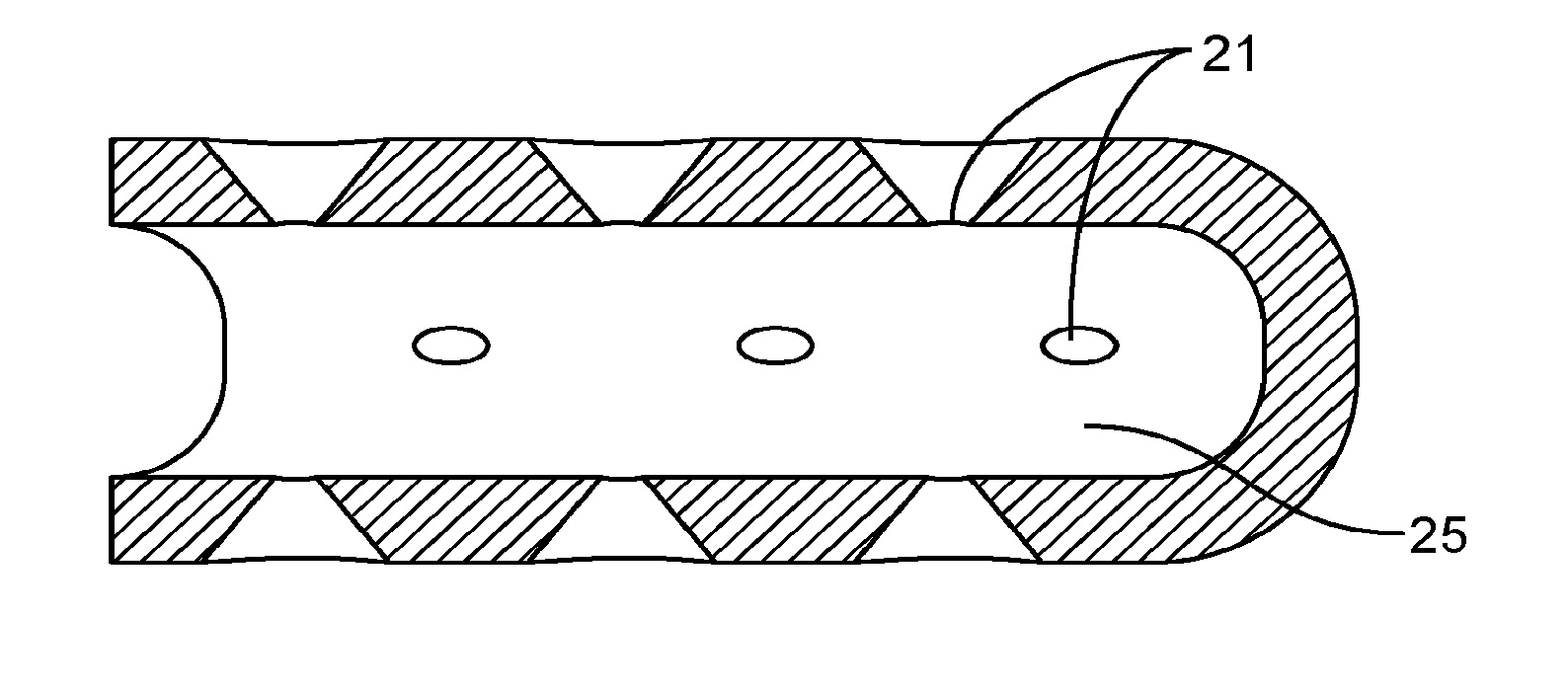
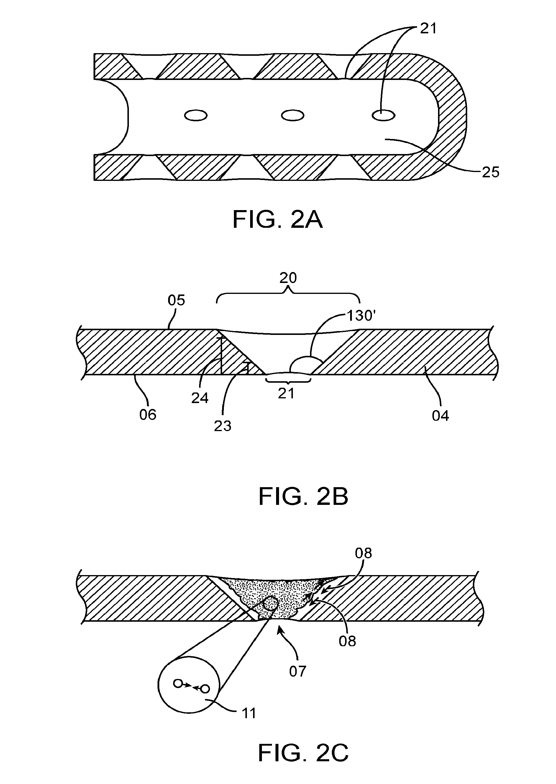
[0027]FIGS. 2A to 2B are illustrations of one embodiment of a clog resistant orifice. In this embodiment, a clog resistant orifice has an inner opening or hole 21 which opens into the lumen 25 of the device or tube. The inner hole is in fluid communication with an outer opening or hole 20 which opens into the outside of the tube, which, in some embodiments, would be in contact with a body cavity for which the tube is either instilling or draining a substance. In the present embodiment, the wall of the tube 04 is cut in a circular or oval shape with the outer wall 24 cut in a larger diameter than the inner wall 23 such that the angle of the wall forming the orifice is angled at greater than 90° in relation to the lumen surface 06 and outer tube surface 05. In the embodiment of the pr...


PUM


Abstract

Devices, apparatuses, systems, and methods for improved clog resistant orifices in medical devices and tubes are provided. A medical tube will comprise a tubular wall having one or more clog resistant orifices. The clog resistant orifices have an outwardly flared orifice wall so as to minimize the occurrence of clogging. The outward flaring, and in some cases inward tapering relative to the outer surface of the tubular wall, can minimize tension and compression forces from forming within the orifice. These forces can otherwise maintain a clog in position within the orifice. The portions of the tubular wall adjacent the orifices may also be more flexible than the remainder of the tubular wall, allowing such portions to bend under pressure or suction to facilitate the shearing away of any clog from the orifice.

Description

CROSS-REFERENCE[0001]This application is a continuation of PCT Application No. PCT / US2013 / 026951, filed Feb. 20, 2013, which claims the benefit of U.S. Provisional Application No. 61 / 633,999, filed Feb. 21, 2012, the full contents of which are incorporated herein by reference.BACKGROUND OF THE INVENTION[0002]The present disclosure relates to medical devices, systems, and methods. In particular, improved medical devices, systems, and methods are provided to improve resistance against the clogging of the various ports or orifices in the various medical devices.[0003]Medical tubes used for removal or delivery of a substance into or out of a body cavity typically have some form of transmission holes near the end of the tube, which transmit the particular substance into or out of the body cavity. Many tubes used such purposes clog frequently. Body secretions, bacterial biofilm, or accumulating residue can tend to build up around these holes or orifices causing clogging and subsequent mal...

Claims


Application Information

Patent Timeline
IPC IPC(8): A61M25/00A61M1/00
CPCA61M25/007A61M1/0078A61M25/0054A61M2025/0019A61M1/83
Inventor MACY, JR., BRADFORD
Owner HOSPI CORP
Why Eureka
Try Eureka