Wind cap for buildings

a technology for buildings and wind caps, applied in the direction of building roofs, transportation and packaging, human health protection, etc., can solve the problems of weakened underlying structures, weakened wind damage to building structures, and increased exposure to further damag

Inactive Publication Date: 2007-12-25
PIERCE RILEY G
View PDF33 Cites 24 Cited by
  • Summary
  • Abstract
  • Description
  • Claims
  • Application Information

AI Technical Summary

Benefits of technology

[0041]Each of the plates includes two pairs of upstanding roller support arms, with a roller installed between each arm of each pair. The roller support arms may be provided in any lengths desired, so long as the arms comprising any given pair are of equal length. The tiedown straps pass over the rollers, with the rollers serving to essentially eliminate friction and asymmetrical forces acting along the lengths of the tiedown straps as they are pulled taut over the roof.
[0042]The base plates provide for the angular adjustment of the support arm attachments thereto, allowing each support arm pair to be adjusted from an orientation normal to the plane of the base plate to some angle to either side of the normal orientation. This allows the arms to be positioned vertically, or at some other angle to extend the rollers outwardly past the eaves and / or gutters of the roof, or to cancel any asymmetric loads on the support arms.
[0043]The present wind cap assembly is physically secured only to the ground anchors disposed to each side of the building structure. The only contact with the building is by the bottom surfaces of the base plates, and the base plates are not mechanically or adhesively attached to the roof. The forces generated by the tiedown straps when they are tightened are sufficient to hold the base plates in place on the roof. This allows the assembly to be quickly installed and removed as required, without need to install or remove nails, screws, adhesives, and / or other attachment means.
[0044]Accordingly, it is a principal object of the invention to provide a wind cap tiedown system for building structures for preventing displacement of the roof due to high winds.
[0047]Still another object of the invention is to provide a wind cap tiedown system having a series of upstanding roller support arms and rollers extending from each of the base plates, to essentially eliminate asymmetrical forces of the tiedown straps passing thereover due to friction.
[0048]It is an object of the invention to provide improved elements and arrangements thereof for the purposes described which is inexpensive, dependable and fully effective in accomplishing its intended purposes.

Problems solved by technology

Wind damage to building structures is a common result when high winds occur, particularly in the case of conventional frame structures having gabled roofs.
When this occurs, the roof, or portions thereof, are often blown away, with the underlying structure being weakened and exposed to further damage when the roof is removed.
The result of this can be uneven forces applied to the cables or straps, with the frictional drag pulling the bearing plates in a direction along the length of the straps or cables, rather than applying a purely compressive load to the roof structure to hold it in place.
Depending upon the specific direction and magnitude of such longitudinal forces along the straps or cables applied to the bearing plates, the forces may be additive to the horizontal wind loads applied to the structure and may weaken the structure further, even though the roof is being held securely in place.
As in the case of the Small roof anchoring system discussed above, Bradley fails to provide any means for reducing the friction of the tiedown lines as they pass through the guides, nor does he provide any means for adjusting the relative positions of the lines and guides.
The blocks merely add weight and break up the airflow over the roof.
Adams fails to provide any form of plate or guide between the tiedown straps and the roof itself.
The tiedowns rest directly upon the surface of the roof, where they may abrade the shingles and / or otherwise damage the roof if any play between the tiedowns and the roof surface occurs.
There would appear to be some problem with entering and exiting the structure with the net in place, as its lower edge appears to be positioned very close to the ground when installed.
In any event, Bimberg et al. fail to disclose any form of rollers which serve to reduce or essentially eliminate friction between the straps or cables and the underlying roof plates.
Moreover, Gaffney does not disclose any rollers or adjustable roller support in the single type of gable plate he provides.
Moreover, no rollers to minimize friction between the cables and the plates and to equalize tensile forces along the cables between plates are provided by Laboy.
In addition, Laboy does not secure his roof tiedown system to the ground, but rather to the underlying building structure.
This system does not provide any means of securing the roof sheathing, as no external tiedown apparatus is provided.
The problem with this system is that in most new construction, the end gables are constructed in the field, and are nailed to the prefabricated, otherwise flat trusses used to support the roof.
Thus, there is no structural continuity extending from the gable eaves overhang to the rest of the roof structure, other than any roof sheathing which may be applied.
Moreover, Thompson does not provide any external anchors extending over the central area of the roof.
Rather, he relies entirely upon two opposed anchors at each end of the gabled eaves, which do not provide significant anchoring strength, as noted above.

Method used


Image

  • Wind cap for buildings
  • Wind cap for buildings
  • Wind cap for buildings

Examples


Embodiment Construction

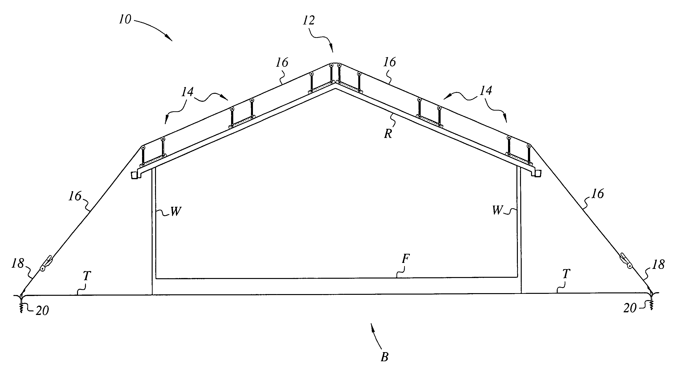
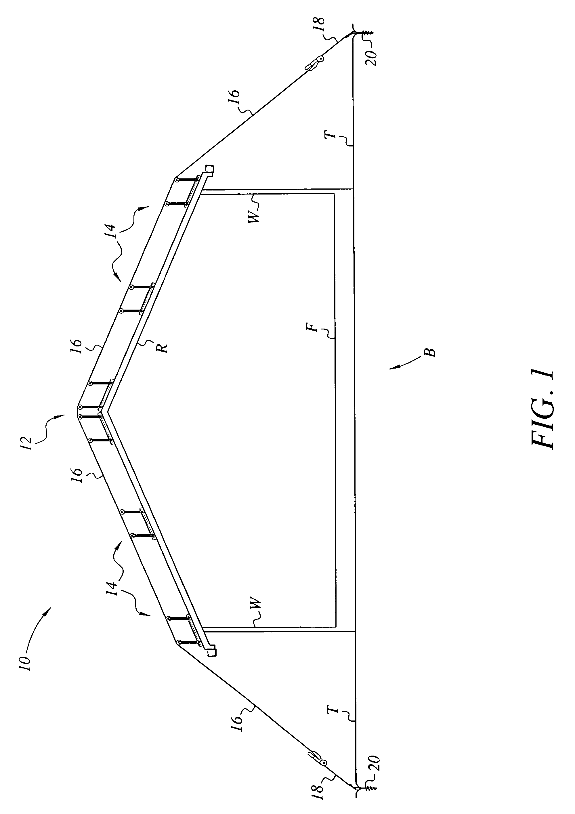
[0056]The present invention comprises an apparatus for securing the roofs of building structures against high winds, as may occur in severe storms and hurricanes. The typical roof structure is secured to the underlying structure primarily due to its weight resting upon the structure, with only a relatively few nails securing the trusses and lower rafter ends of the roof to the underlying top plates in a typical frame building construction. However, the typical gabled roof configuration found in most smaller structures is capable of acting as a crude airfoil, and can generate enough lifting forces in high winds to cause the entire roof to separate from the underlying structure. In other cases, winds may generate sufficient force to lift portions of the roof sheathing from the underlying rafters.

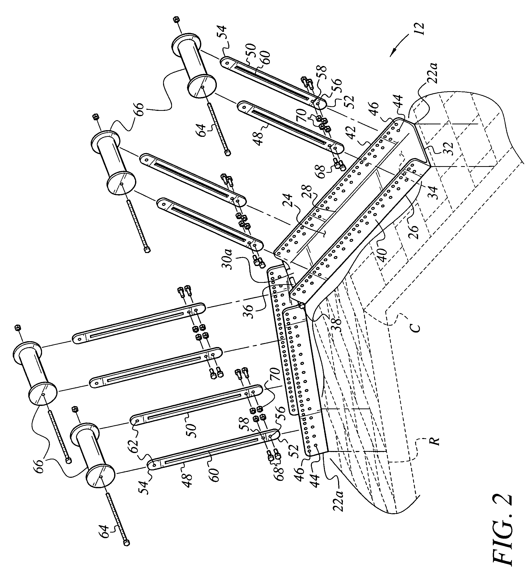
[0057]The present invention provides a solution to this problem by means of a series of tiedown straps, each of which passes over a series of base plates removably placed upon the roof. The en...


PUM


Abstract

A wind cap for buildings serves to anchor a building structure securely to the underlying terrain. The wind cap is a series of base plates which are temporarily and removably placed upon the roof of a structure, with a corresponding series of tiedown straps secured over the plates and attached to ground anchors on opposite sides of the structure. Two of the base plate components may be hinged together along their common edges for placement over the ridge line of the roof. Single plates are placed along the eaves and at intermediate points of the roof span. Each plate includes at least one pair of roller support arms adjustably extending upwardly therefrom, with a roller installed between each arm pair. The rollers eliminate the drag of the tiedown strap passing thereover, thereby eliminating asymmetrical loads on the underlying plates and roof as the straps are tightened.

Description

CROSS-REFERENCE TO RELATED APPLICATION[0001]This application claims the benefit of U.S. Provisional Patent Application Ser. No. 60 / 534,409, filed Jan. 7, 2004.BACKGROUND OF THE INVENTION[0002]1. Field of the Invention[0003]The present invention relates generally to assemblies and systems for securing roofs to their underlying structures in order to avoid damage due to high winds. More particularly, the present invention comprises a series of tiedown straps which are secured to corresponding ground anchors on opposite sides of a building structure, and which pass over corresponding bearing plates placed upon the roof structure. The bearing plates each include one or more rollers extending upwardly therefrom, upon which the tiedown straps bear.[0004]2. Description of the Related Art[0005]Wind damage to building structures is a common result when high winds occur, particularly in the case of conventional frame structures having gabled roofs. The roofs of such structures generally depen...

Claims


Application Information

Patent Timeline
Patent Type & Authority Patents(United States)
IPC IPC(8): E04B7/00E04H9/14
CPCE04H9/14Y10S52/12Y10S52/11Y02A50/00
Inventor PIERCE, RILEY G.
Owner PIERCE RILEY G
Why Eureka
Try Eureka