Electrical connector

a technology of electrical connectors and connectors, applied in the direction of coupling contact members, fixed connections, coupling device connections, etc., can solve the problems of contact failure, inability to allow the recess provided in the base connector to have a sufficient depth,

Active Publication Date: 2006-10-10
JST MFG CO LTD
View PDF18 Cites 25 Cited by
  • Summary
  • Abstract
  • Description
  • Claims
  • Application Information

AI Technical Summary

Benefits of technology

[0039]The statement “the socket connector is inserted into and removed from the recess of the base connector in insertion and removal directions perpendicular to the attachment face of the print board” implies that the socket connector is a so-called top-mounted connector. In addition to the top-mounted connector, there is a so-called side-mounted connector. In case of a side-mounted connector, a socket connector is inserted into and removed from a base connector in insertion and removal directions parallel to the attachment face of a print board. In a wire-to-board connector, a top-mounted connector advantageously increases the degree of freedom of arrangement of the connector on a print board. On the other hand, in case of a side-mounted connector, there is a restriction on a base connector which must be disposed at the end of a print board.
[0048]The socket contact according to the invention is configured to have the pair of first locking mechanisms installed at both sides of the socket housing and further have the second locking mechanisms installed in a position opposite the direction of extension of the lead wires, thereby preventing movement of the socket contact having a lower height about a point of support, which movement is due to the movement of lead wires, associated with a pair of locking mechanisms, and observed in the conventional electrical connector. Accordingly, the electrical connector describe above allows secure engagement between the socket connector and the base connector without being affected by lead wires extending from the socket connector.
[0052]It could be concluded that providing the pair of mating depressions in the pair of inner walls of the base housing facilitates thinning of the pair of sidewalls defining the recess and insertion / removal of the socket connector. Further, it could be concluded that providing the pair of mating depressions in the pair of first inner walls of the base housing enables compaction of the base housing (reduction in mounting area).
[0056]The subject of the invention is to provide an electrical connector capable of eliminating a force that causes the movement of the socket connector and that is considered substantially proportional to the number of arrangements of the opponent contacts and the number of the lead wires corresponding to the number of arrangements. For example, in case of two-pole connector, the number of grooves is “1” and in case of three-pole connector, the number of grooves is “2”. Accordingly, if a designer is able to know the number of grooves per pole of the electrical connector by simply counting the number of opponent contacts, the designer can conveniently design a series of multi-pole connectors based on the inventive electrical connector.
[0058]The opponent contacts are a metallic plate that is, for example, pressed into and fixed to the sidewall of the base housing. Further, it could be thought that the grooves are formed between the arrangements of the opponent contacts and therefore the rigid opponent contacts serve to prevent deformation of the walls forming the groove and interposed between poles.
[0059]The electrical connector of the invention is configured so that a pair of first locking mechanisms are installed in opposing walls forming a recess of a base connector and a pair of outer walls of a socket connector facing the opposing walls and further a second locking mechanism is installed in an inner wall forming a depression opposite the direction of extension of lead wires and an outer wall of the socket connector facing the inner wall, thereby preventing movement of the socket contact having a lower height about a point of support, which movement is due to the movement of lead wires, associated with a pair of locking mechanisms, and observed in the conventional electrical connector. Accordingly, the electrical connector provided described above allows secure engagement between the socket connector and the base connector without being affected by lead wires extending from the socket connector.

Problems solved by technology

In this case, it becomes impossible to allow the recess provided in the base connector to have a sufficient depth.
Further, when such connectors having a lower height are used, it would be undesirable and expected that the lead wires extending from the socket connector act to cause the movement of the socket connector about a point of support, which movement is associated with a pair of locking mechanisms installed at both sides of the socket connector.
This implies that the movement of the socket connector eventually leads to contact failure.

Method used


Image

  • Electrical connector
  • Electrical connector
  • Electrical connector

Examples


Embodiment Construction

[0080]Preferred embodiments of the invention will be explained below with reference to the accompanying drawings.

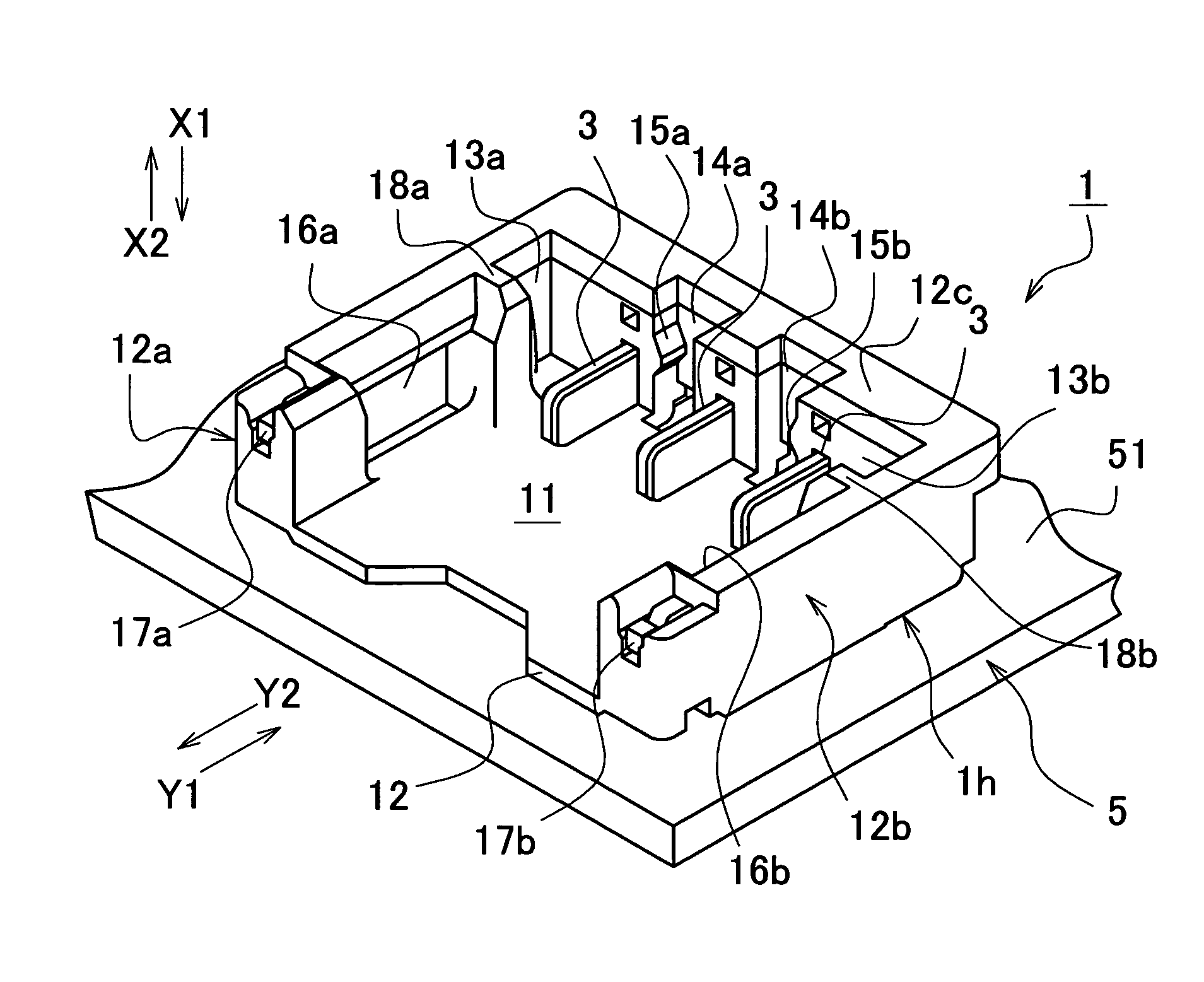
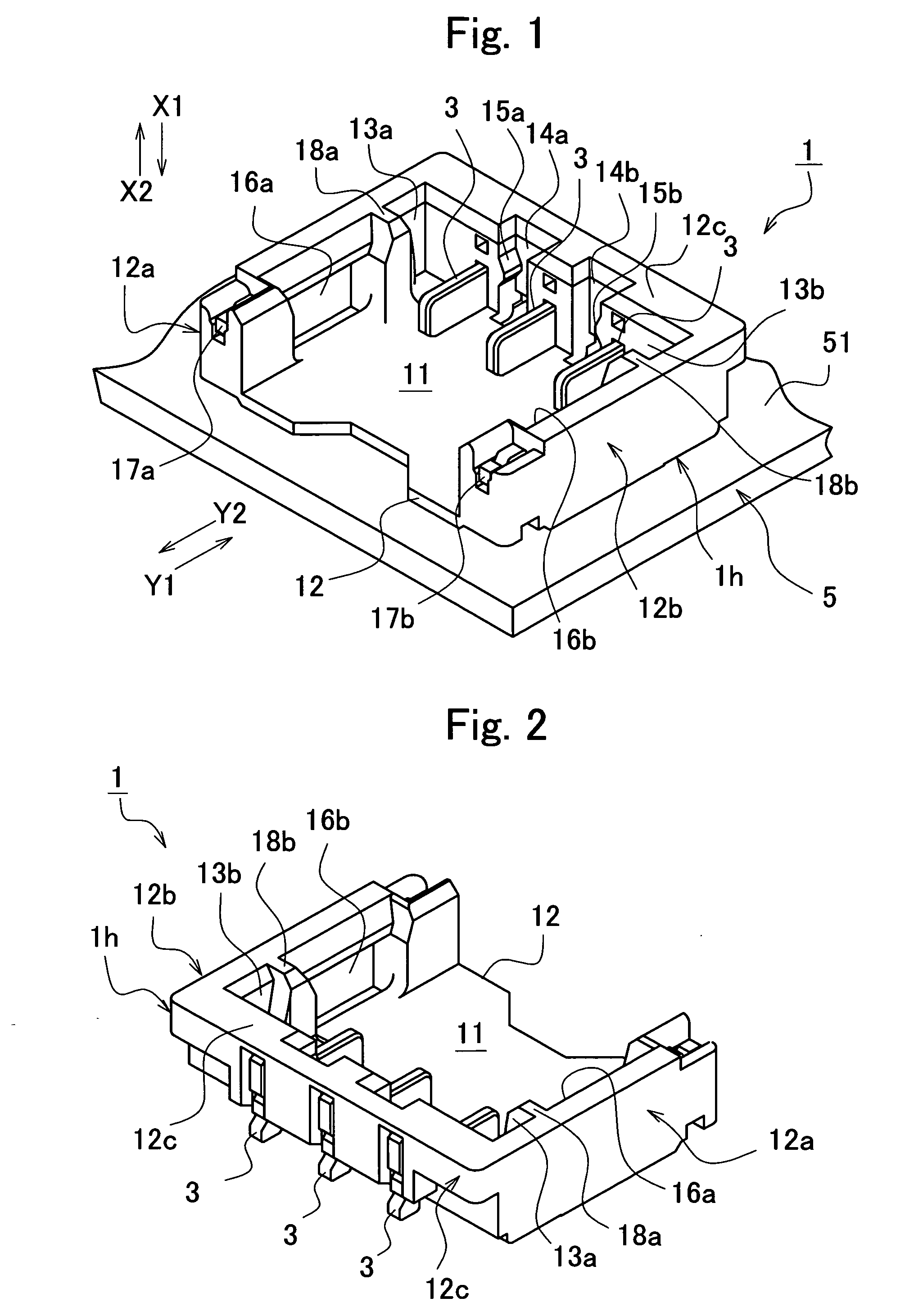
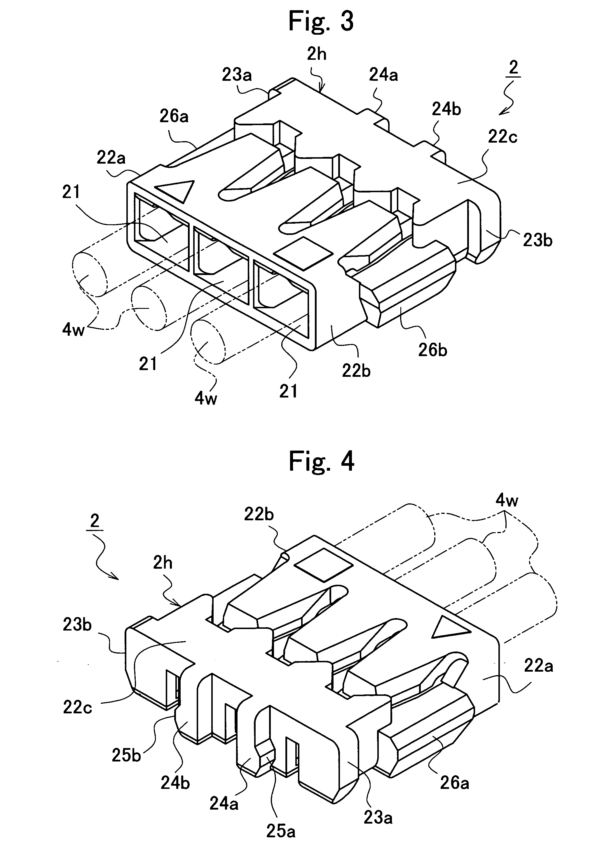
[0081]FIG. 1 is a perspective outline view of a base connector according to a first embodiment of the invention. FIG. 2 is a perspective outline view of the base connector according to said first embodiment. FIG. 2 shows the base connector viewed from the side opposite that illustrated in FIG. 1. FIG. 3 is a perspective outline view of a socket connector according to said first embodiment. FIG. 4 is a perspective outline view of the socket connector according to said first embodiment. FIG. 4 shows the socket connector viewed from the side opposite that illustrated in FIG. 3.

[0082]FIGS. 5A to 5F illustrate outlines and cross-sectional views of the base connector according to said first embodiment. FIG. 5A is a plan view of the base connector, FIG. 5B is a front view of the base connector, FIG. 5C is a left side view of FIG. 5A, FIG. 5D is a right side view of FIG. 5A, FIG....


PUM


Abstract

An electrical connector comprises: a base connector having a base housing and fixed to a print board, the base housing defining a recess having a plurality of plane opponent contacts; a socket connector having a socket housing that houses a plurality of socket contacts to be connected with the opponent contacts, the socket connector inserted into and removed from the recess; a plurality of lead wires extending in a direction substantially parallel to an attachment face of the print board; a pair of first locking mechanisms provided with the base housing and the socket housing, respectively, the first locking mechanisms engaging each other in a direction perpendicular to the direction of extension of the lead wires; and a pair of second locking mechanisms provided with the base housing and the socket housing, respectively, the second locking mechanisms engaging each other in a direction opposite the direction of extension of the lead wires.

Description

BACKGROUND OF THE INVENTION[0001]1. Field of the Invention[0002]Priority is claimed on Japanese Patent Application No. 2004-317951, filed Nov. 1, 2004, the content of which is incorporated herein by reference.[0003]The present invention relates to an electrical connector. In particular, the invention relates to an electrical connector having a locking mechanism for maintaining engagement between two connectors, one of which is a base connector fixed to a print board and the other of which is a socket connector inserted into and removed from the base connector.[0004]2. Description of the Related Art[0005]Nowadays, a compact-sized portable electronic device such as DSC (Digital Still Camera), cellular phone, CD player, or MD player incorporates a battery. To supply electric power from the battery to a circuit board (print board) installed in said electronic device, an extremely small connector, so called CSP (Chip Size Package) type wire to board connector, has been employed.[0006]An ...

Claims


Application Information

Patent Timeline
Patent Type & Authority Patents(United States)
IPC IPC(8): H01R13/10
CPCH01R13/11H01R13/567H01R12/75H01R13/6273H01R4/185H01R12/57
Inventor MASAKI, KATSUYUKIKODAMA, SHINICHI
Owner JST MFG CO LTD
Why Eureka
Try Eureka