
Air conditioner indoor unit

A technology for air-conditioning indoor units and evaporators, which is applied to air-conditioning systems, mechanical equipment, and air quality improvement. It can solve the problem of small air volume at the tuyere and achieve the effect of ensuring comfort

Pending Publication Date: 2021-04-13
GREE ELECTRIC APPLIANCES INC
View PDF0 Cites 0 Cited by
  • Summary
  • Abstract
  • Description
  • Claims
  • Application Information

AI Technical Summary

Problems solved by technology

[0004] The main purpose of the present invention is to provide an air conditioner indoor unit to solve the technical problem in the prior art that the air volume at the tuyere is small due to the sterilizing module of the air conditioner indoor unit being arranged at the tuyere

Method used


Image

  • Air conditioner indoor unit
  • Air conditioner indoor unit
  • Air conditioner indoor unit

Examples


Embodiment Construction

[0035] It should be noted that, in the case of no conflict, the embodiments in the present application and the features in the embodiments can be combined with each other. The present invention will be described in detail below with reference to the accompanying drawings and examples.

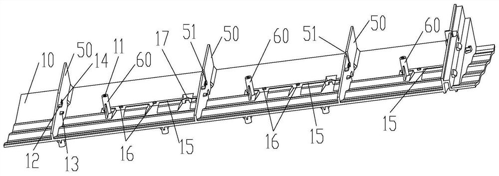
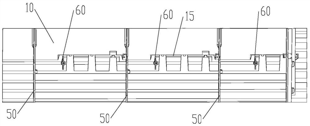
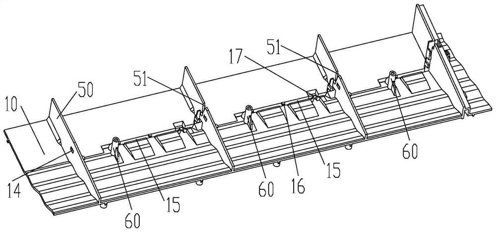
[0036] Such as Figure 1 to Figure 12 As shown (the arrows in the drawings represent the flow direction of the airflow), the embodiment of the present invention provides an air-conditioning indoor unit, which includes a bottom case 10, a panel 20, an evaporator 30 and a sterilization module 40, and the panel 20 Installed on the bottom case 10 , the bottom case 10 is used to be installed on an installation base, specifically, the installation base here can be a wall or any fixed structure capable of installing the bottom case 10 . The evaporator 30 is disposed between the bottom case 10 and the panel 20 , the sterilization module 40 is disposed on the bottom case 10 , and the sterilization modu...


PUM


Abstract

The invention provides an air conditioner indoor unit which comprises a bottom shell, a panel, an evaporator and a sterilization module. The panel is installed on the bottom shell, and the bottom shell is used for being installed on an installation foundation; the evaporator is arranged between the bottom shell and the panel; and the sterilization module is arranged on the bottom shell, and the sterilization module and the evaporator are oppositely arranged, so that the sterilization module sterilizes air flowing through the evaporator. By means of the technical scheme, the technical problem that in the prior art, due to the fact that a sterilization module of an air conditioner indoor unit is arranged at an air port, the air volume at the air port is small can be solved.

Description

technical field [0001] The present invention relates to the technical field of air conditioner indoor units, in particular to an air conditioner indoor unit. Background technique [0002] At present, with the gradual improvement of living standards and the increase in the frequency of use of air-conditioning indoor units, in order to improve the quality of indoor air, the indoor air is generally sterilized by setting a sterilizing structure in the air-conditioning indoor unit. In the prior art, the germicidal structure used more often is UVC germicidal lamp, and the UVC germicidal lamp is generally installed at the position of the tuyere. [0003] However, adopting such a setting method will cause the UVC germicidal lamp at the tuyere to have a certain impact on the air volume and wind speed at the tuyere, affecting the air inlet and outlet of the tuyere, thereby affecting the comfort of use. Contents of the invention [0004] The main purpose of the present invention is ...

Claims


Application Information

Patent Timeline
Patent Type & Authority Applications(China)
IPC IPC(8): F24F1/0063F24F1/0076F24F8/22F24F13/30
CPCF24F13/30F24F1/0063F24F1/0076Y02A50/20
Inventor 郭强成凯潘正伟王成龙唐雪
Owner GREE ELECTRIC APPLIANCES INC
Learn More