
Cable shearing device for relay protection

A shearing device and relay protection technology, which is applied in the field of cable shearing devices for relay protection, can solve the problems of low manual assembly efficiency, decreased fit of movable shafts, and low quality

Active Publication Date: 2021-04-16
YANTAI MUPING POWER SUPPLY CO OF STATE GRID SHANDONG ELECTRIC POWER CO +1
View PDF9 Cites 1 Cited by
  • Summary
  • Abstract
  • Description
  • Claims
  • Application Information

AI Technical Summary

Problems solved by technology

[0007]Aiming at the deficiencies of the prior art, the present invention provides a cable cutting device for relay protection, which is equipped with conveniently trapped cables installed on the rotating shaft, cable cutting The process reduces the difficulty of cutting and saves time and effort, it is convenient to fix a single cable, and the equipment is stable during the cutting process. It solves the problem of low manual assembly efficiency and low quality in the traditional bearing assembly process. Uniformity will lead to a decrease in the balance between the bearing and the shaft, and the direction of the beating is not vertical, which will cause the inside of the bearing to be subjected to the lateral extrusion force of the active shaft, which will lead to the problem that the inner ring of the bearing expands and the fitting degree of the active shaft decreases.

Method used


Image

  • Cable shearing device for relay protection
  • Cable shearing device for relay protection
  • Cable shearing device for relay protection

Examples


Embodiment Construction

[0031] The following will clearly and completely describe the technical solutions in the embodiments of the present invention with reference to the drawings in the embodiments of the present invention.

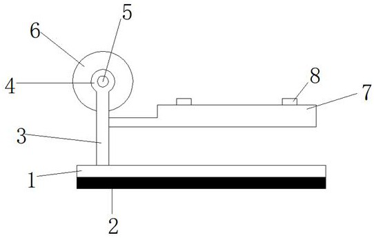
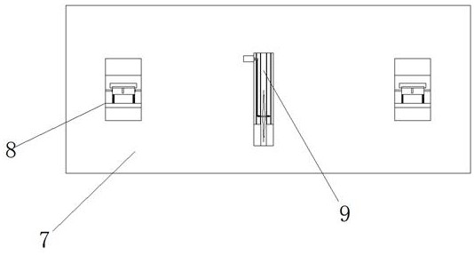
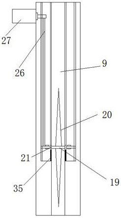
[0032] see Figure 1-7 , a cable shearing device for relay protection, comprising a base 1, the bottom surface of the base 1 is provided with a non-slip mat 2, the top of the base 1 is provided with a coil fixing assembly, and the coil fixing assembly consists of a fixed disc 4, a rotating shaft 5, and a retaining plate 6 , a sleeve 29, a first adapter 31, a second adapter 32, and a collar 34. A single wire fixing assembly is arranged symmetrically on one side of the coil fixing assembly. The single wire fixing assembly consists of a retainer 8, a connecting block 11, The fixed block 12, the first spring 13, the block 14, the mounting plate 15, the second spring 16, and the pressing block 17 are composed of a shearing assembly between the two single wire fixing assemblies, and...


PUM


Abstract

The invention discloses a cable shearing device for relay protection. The cable shearing device for relay protection comprises a base, the lower surface of the base is provided with an antiskid pad, the top of the base is provided with a coil fixing assembly, the coil fixing assembly consists of a fixed disc, a rotating shaft, a baffle disc, a sleeve, a first adapter, a second adapter, and a lantern ring, single wire fixing assemblies are symmetrically arranged on one side of the coil fixing assembly, each single wire fixing assembly is composed of a fixator, a connecting block, a fixing block, a first spring, a check block, an installation plate, a second spring and a pressing block, and a shearing assembly is arranged between the two single wire fixing assemblies. The cable shearing device for relay protection can achieve the advantages that a trapped cable can be conveniently installed on the rotating shaft, the cutting difficulty is reduced in the cable cutting process, time and labor are saved, a single cable can be conveniently fixed, and equipment is stable in the shearing process.

Description

technical field [0001] The invention relates to the technical field of cable processing, in particular to a cable cutting device for relay protection. Background technique [0002] Cable cutting is the main way for power companies to divide cables, extending the bundled cables a little bit. [0003] Before the cable is cut, the bundled cables need to be installed on the rotating shaft, and the existing rotating shaft is not easy to install. [0004] In the process of cable cutting, a horse rotating device is now required. The existing rotating device uses a hydraulic device to move the motor up and down, and the motor drives the rotating blade to cut the cable. On the one hand, the production cost of the equipment is increased, and on the other hand, the Cutting is difficult, time-consuming and labor-intensive. [0005] Cables are cut according to actual needs. The existing methods of cutting cables cannot effectively tighten and fix the cut parts in the aspect of conveyin...

Claims


Application Information

Patent Timeline
Patent Type & Authority Applications(China)
IPC IPC(8): B21F11/00B25B11/00
Inventor 高虎军于海东孙冰孙鹏程国庆张志浩姜姝彤赵晓轲侯成君刘海波彭锐
Owner YANTAI MUPING POWER SUPPLY CO OF STATE GRID SHANDONG ELECTRIC POWER CO
Learn More