

Hydraulic power speed increaser
Patent Information
- Authority / Receiving Office
- CN · China
- Current Assignee / Owner
- 广东国宏智能装备有限公司
- Publication Date
- 2021-04-16
Smart Images
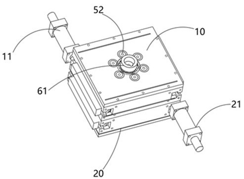
Figure 1 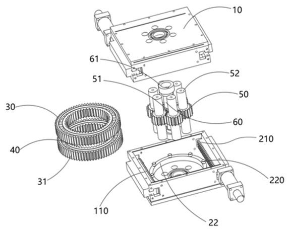
Figure 2 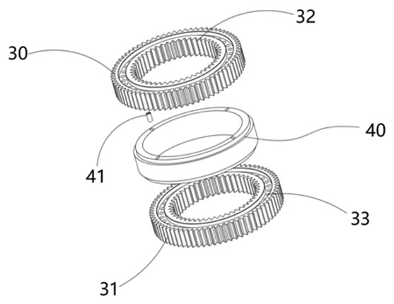
Figure 3
Abstract
Description
technical field
[0001] The invention relates to the technical field of speed increasers, in particular to a hydraulic power speed increaser. Background technique
[0002] The speed increaser is an important part of complete sets of equipment for wind power generation, aircraft, and hydraulic high-pressure plunger pumps. However, at present, the speed increasers at home and abroad all use the motor structure, and the speed increase ratio is small, so that the driving torque cannot meet the demand. Contents of the invention
[0003] In order to solve the above problems, the object of the present invention is to provide a hydraulic power speed increaser that is driven by hydraulic pressure and utilizes a planetary gear set to increase the gear ratio.
[0004] The purpose of the present invention adopts following technical scheme to realize:
[0005] A hydraulic power speed increaser, including a speed increaser, a planetary gear set, an impeller and a rotating shaft, the sp...