Self-cleaning light-transmitting window for urban high-rise building

A high-rise building, self-cleaning technology, used in construction, cleaning equipment, building components, etc., can solve problems such as poor effect, water stains, large labor force, etc.

Inactive Publication Date: 2021-04-20
王利
View PDF8 Cites 3 Cited by
  • Summary
  • Abstract
  • Description
  • Claims
  • Application Information

AI Technical Summary

Problems solved by technology

[0003] The traditional cleaning method is generally to scrub the glass at high altitude by the staff with a hanging basket or a waist-tied rope. This method not only consumes a lot of labor, but also has certain dangers due to the high floor. Now there are some Automatic cleaning device, but simply wipe with cleaning solution and sponge, it is easy to leave water stains on the glass during cleaning, and water stains will be left after the water stains dry, which will affect the cleanliness of the glass and make the cleaning effect poor. Therefore, we need to design a self-cleaning light-transmitting window for urban high-rise buildings to solve the above problems

Method used


Image

  • Self-cleaning light-transmitting window for urban high-rise building
  • Self-cleaning light-transmitting window for urban high-rise building
  • Self-cleaning light-transmitting window for urban high-rise building

Examples


Embodiment 1

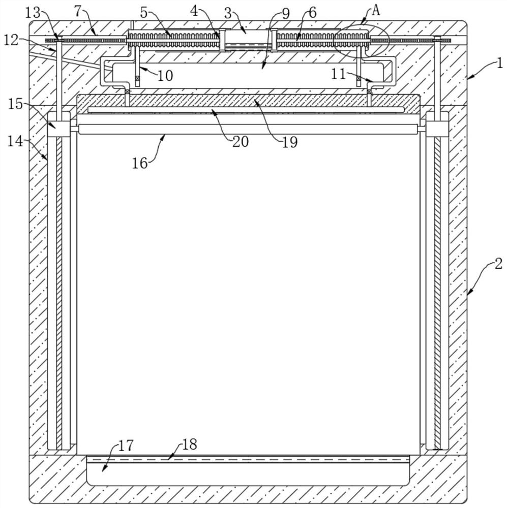
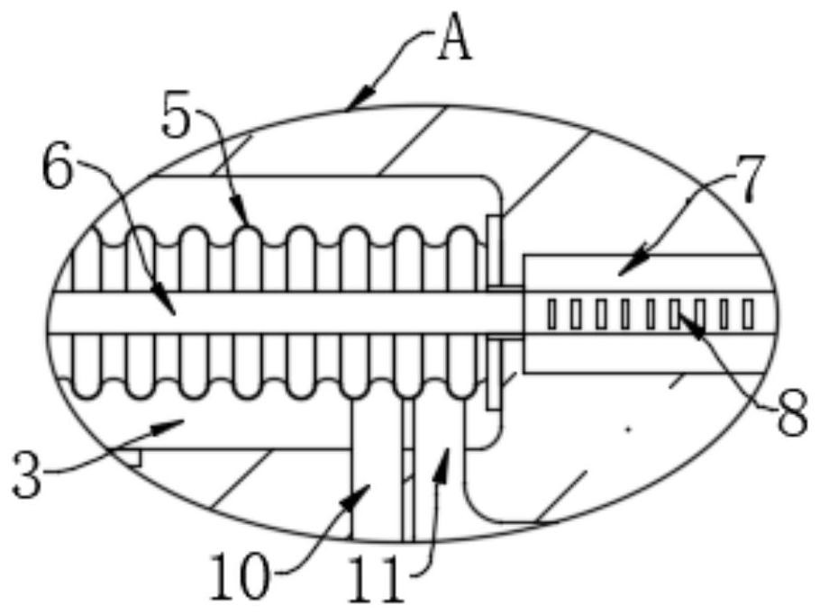
[0027] refer to Figure 1-2 , a self-cleaning light-transmitting window for urban high-rise buildings, including a window frame, the window frame is composed of two installation blocks 1 and two vertical plates 2, the size of the two installation blocks 1 can be designed according to the actual situation, and can be two There are two installation blocks 1 with different sizes, the two vertical plates 2 are located between the two installation blocks 1, glass is installed in the window frame, and a trigger cavity 3 is opened in the upper installation block 1, and inside the trigger cavity 3 A low-boiling point solution is provided. The low-boiling point solution can be organic matter such as aldehydes and ethers. The boiling point is generally between 20 and 35 degrees. The upper end of the mounting block 1 below is provided with a collection tank 17, which is convenient for collecting dust. , the notch place of collection tank 17 is equipped with dust-proof net 18, and dust-pr...

Embodiment 2

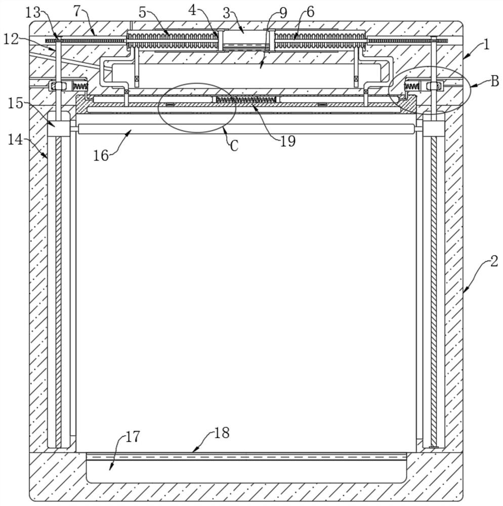
[0038] refer to Figure 3-6 The difference between this embodiment and Embodiment 1 is that it also includes two blowing mechanisms, the two blowing mechanisms are respectively arranged on the left and right sides of the liquid storage chamber 9, and the blowing mechanisms include openings in the installation block 1 located above The rotating chamber 21 of the rotating rod 12 runs through the rotating chamber 21, and the part of the rotating rod 12 located in the rotating chamber 21 is provided with a one-way bearing 23. The one-way bearing 23 is a prior art, and can rotate freely in one direction. A bearing that is locked in the other direction. Two fan blades 22 are fixedly connected to the one-way bearing 23, one of the fan blades 22 is magnetic, and the magnetic fan blade 22 repels the adjacent surface of the magnetic piston 24, and the rotating chamber 21 There is a magnetic piston 24 for moving left and right. The side of the magnetic piston 24 away from the fan blade 2...


PUM


Abstract

The invention discloses a self-cleaning light-transmitting window for urban high-rise building.The window comprises: a window frame which is composed of two installation blocks and two vertical plates, wherein the two vertical plates are both located between the two installation blocks, glass is installed in the window frame, a trigger cavity is formed in an installation block located on the upper portion, and a low-boiling-point solution is arranged in the trigger cavity; and two triggering mechanisms which are arranged on the left side and the right side of the low-boiling-point solution correspondingly, and comprise pushing plates arranged in the trigger cavity. When in use, the equipment does not need to be started by a worker, only a cleaning agent needs to be added at regular time, labor consumption is reduced, meanwhile, residual water spots on the surface of glass can be treated during cleaning, and the cleaning effect is improved.

Description

technical field [0001] The invention relates to the field of automatic cleaning, in particular to a self-cleaning light-transmitting window for urban high-rise buildings. Background technique [0002] With the development of society, there are more and more high-end buildings in big cities, and there are more and more high-rise and super high-rise buildings. The exterior walls of many buildings are decorated with large glass, which is easily polluted by the external environment and needs to be scrubbed frequently; [0003] The traditional cleaning method is generally to scrub the glass at high altitude by the staff with a hanging basket or a waist-tied rope. This method not only consumes a lot of labor, but also has certain dangers due to the high floor. Now there are some Automatic cleaning device, but simply wipe with cleaning liquid and sponge, it is easy to leave water stains on the glass during cleaning, and water stains will be left after the water stains dry, which wi...

Claims


Application Information

Patent Timeline
Patent Type & Authority Applications(China)
IPC IPC(8): A47L1/02E06B7/28
Inventor 王利郭保林
Owner 王利
Why Eureka
Try Eureka