
Excavator traveling high-low speed switching control method and system

A control method and technology for switching systems, applied in the field of hydraulic control systems, can solve problems such as accidental switching, affecting the stability of the excavator, and increasing the labor intensity of operators

Active Publication Date: 2021-04-20
中联重科土方机械有限公司 +1
View PDF6 Cites 0 Cited by
  • Summary
  • Abstract
  • Description
  • Claims
  • Application Information

AI Technical Summary

Problems solved by technology

Moreover, when operating in complex working conditions, as the operating conditions continue to change, the operator needs to frequently switch between walking modes, which increases the labor intensity of the operator and makes the operation less convenient.
[0005] Recently, some excavator high-low speed switching systems with automatic shifting function have appeared, but the existing high-low speed switching systems of excavators usually only set a reference value for controlling the travel motor travel motor pressure. When the excavator travel pressure is within this Frequent changes near the set reference value will cause the travel motor to switch drive modes frequently, affecting the stability of the excavator's travel
Existing excavator high-low speed switching systems usually use the hydraulic pressure of the traveling motor as the driving mode switching standard, and the change of the fuselage angle when the excavator is working in a non-traveling state will also cause changes in the hydraulic pressure of the traveling motor, resulting in walking Accidental switching of motor-for-drive mode

Method used


Image

  • Excavator traveling high-low speed switching control method and system
  • Excavator traveling high-low speed switching control method and system
  • Excavator traveling high-low speed switching control method and system

Examples


Embodiment Construction

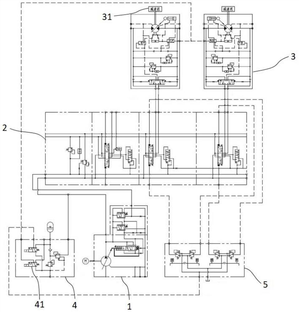
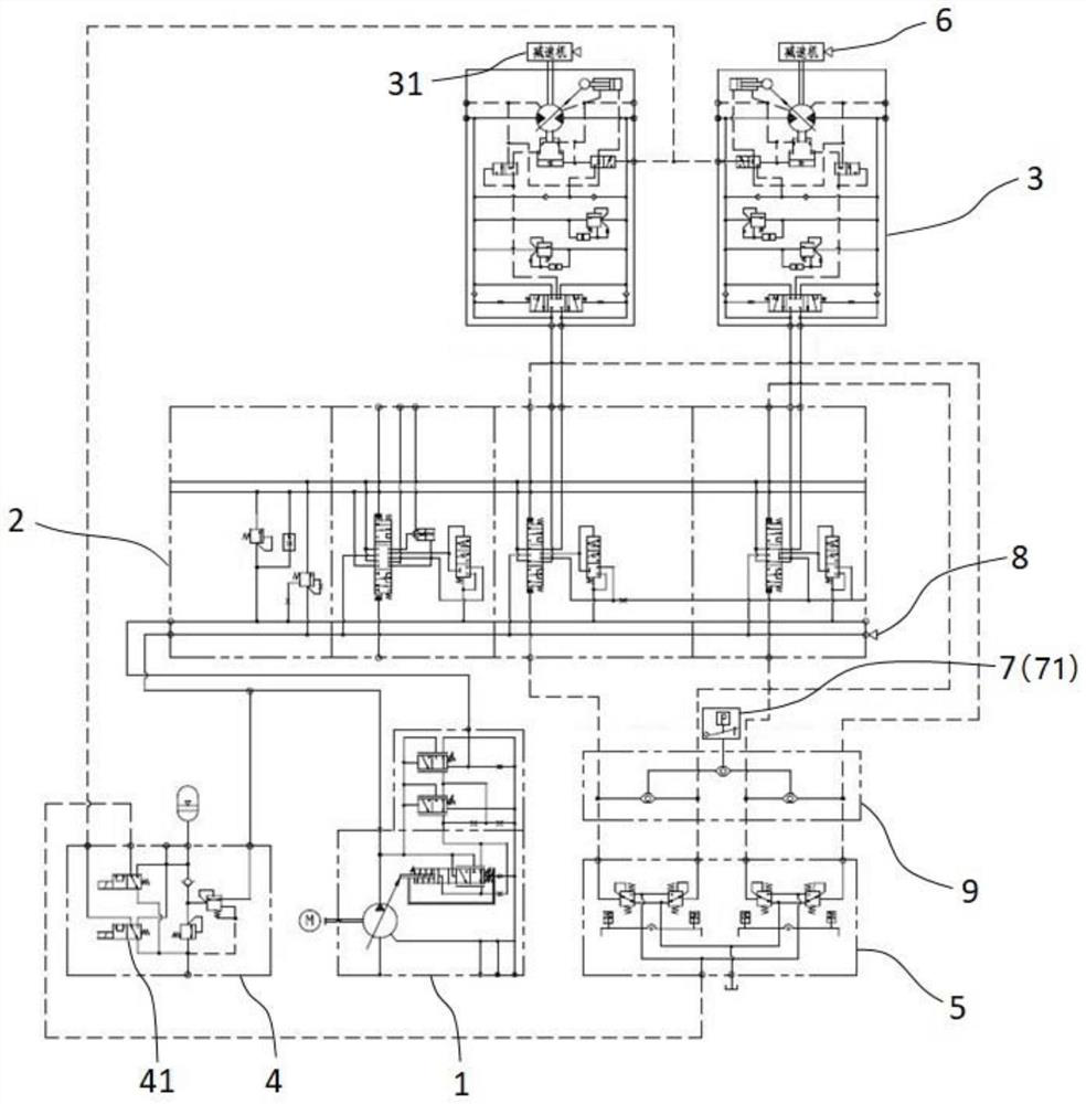
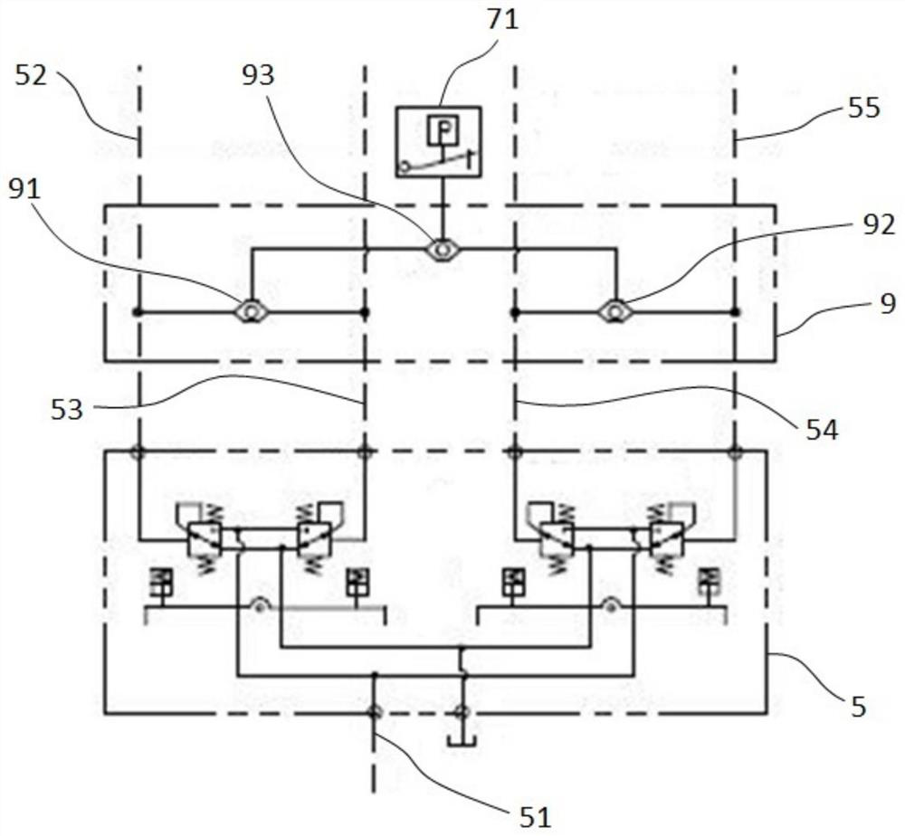
[0039] Specific embodiments of the present invention will be described in detail below in conjunction with the accompanying drawings. It should be understood that the specific embodiments described here are only used to illustrate and explain the present invention, and are not intended to limit the present invention.

[0040] The terms "first", "second" and "third" are used for descriptive purposes only, and cannot be interpreted as indicating or implying relative importance or implicitly specifying the number of indicated technical features. The features of "a", "second", and "third" may explicitly or implicitly include one or more of said features.

[0041] In the description of the present invention, it should be noted that unless otherwise specified and limited, the terms "installation", "setting", and "connection" should be understood in a broad sense, for example, it can be a fixed connection or a detachable connection. A connection, or an integral connection; it may be...


PUM


Abstract

The invention further discloses an excavator traveling high-low speed switching control method. The excavator traveling high-low speed switching control method comprises the following steps that S1, the traveling speed of an excavator is detected and compared with the speed reference section; S2, load pressure of a traveling motor of the excavator is detected, and the load pressure is compared with the pressure reference section; S3, driving state information of the traveling motor is detected; and S4, when the traveling motor is in a driving state, the traveling speed of the excavator is located in the low-speed reference section, and the load pressure of the traveling motor is located in the low-pressure reference section, the driving mode of the traveling motor is controlled to be a high-speed driving mode; when the traveling motor is in a driving state, the traveling speed of the excavator is located in the high-speed reference section, and the load pressure of the traveling motor is located in the high-pressure reference section, the driving mode of the traveling motor is controlled to be a low-speed driving mode; and otherwise, the current driving mode of the traveling motor is kept unchanged. According to the excavator traveling high-low speed switching control method, the switching is convenient, stable and reliable. The invention further discloses an excavator traveling high-low speed switching system.

Description

technical field [0001] The invention relates to a hydraulic control system, in particular to a high and low speed switching control method for an excavator. In addition, the invention also relates to an excavator walking high and low speed switching system. Background technique [0002] As an important equipment in engineering construction, excavators play an extremely important role in the construction of industrial and civil buildings, transportation, water conservancy and electric power engineering, mining and military engineering, and have been widely used in related engineering fields. [0003] At present, the travel motors used in crawler excavators at home and abroad are usually two-stage speed-regulating motors. The travel motor has two driving modes: high speed and low speed, and the displacement can be changed by changing the swing angle of the travel motor swash plate; In the drive mode, it can provide a large torque to meet the needs of the excavator working in ...

Claims


Application Information

Patent Timeline
IPC IPC(8): E02F9/22
Inventor 李文举张磊魏焕焕杨正维李岳华
Owner 中联重科土方机械有限公司
Learn More