Damping mounting base of electrical equipment for wind power generation

A technology for installing bases and electrical equipment, applied in mechanical equipment, springs/shock absorbers, non-rotational vibration suppression, etc., can solve problems such as large swings and vibrations

Pending Publication Date: 2021-04-20
新疆吐鲁番广恒新能源有限公司
View PDF9 Cites 0 Cited by
  • Summary
  • Abstract
  • Description
  • Claims
  • Application Information

AI Technical Summary

Problems solved by technology

[0006] During the rotation of the wind rotor, the generator and other electrical equ

Method used


Image

  • Damping mounting base of electrical equipment for wind power generation
  • Damping mounting base of electrical equipment for wind power generation
  • Damping mounting base of electrical equipment for wind power generation

Examples


Embodiment 1

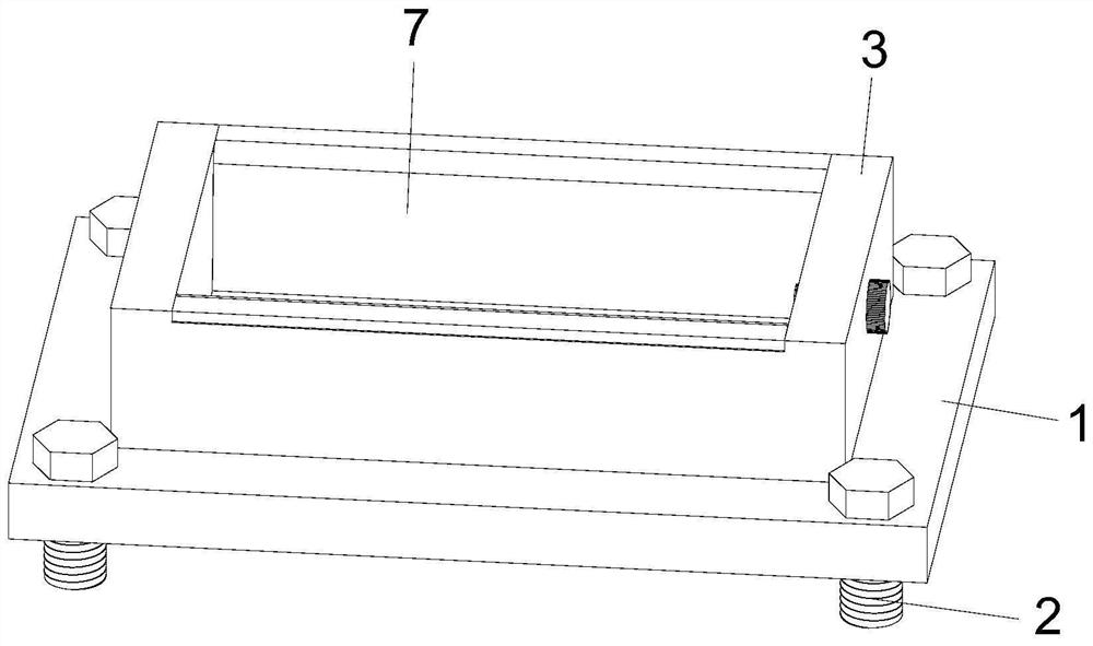
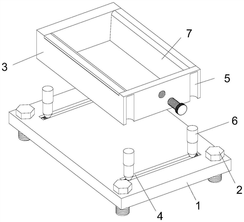
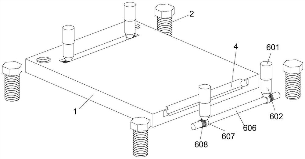
[0028] Please refer to Figures 1-4, a shock-absorbing mounting base for electrical equipment used in wind power generation, including a mounting base 1, with bolts 2 downwards at the four corners of the top surface of the mounting base 1, and a fixing frame 3 in the middle of the top surface of the mounting base 1 , the position of the top surface of the mounting seat 1 relative to the bottom surface of the fixed frame 3 is in a front-rear symmetrical structure, and a chute 4 is provided, and the four corners of the bottom surface of the fixed frame 3 are set up with a limit groove 5 relative to the position of the chute 4, and the inside of the limit groove 5 is provided. Vibration component 6, fixed frame 3 is provided with fixed component 7 inside.

[0029] The bottom surface of the fixing frame 3 is in clearance fit with the top surface of the mounting base 1 .

[0030] The shock absorbing assembly 6 includes a sleeve 601, which is slidably connected to a limit tube 602 in...

Embodiment 2

[0035] Please refer to Figure 5, the difference in the basis of Embodiment 1 is that the fixing assembly 7 includes two fixing plates 701, the fixing plates 701 are symmetrically arranged inside the fixing frame 3, and the fixing plates 701 are arranged in an L-shaped structure, The fixed plate 701 inwall is inclined result setting, and the fixed plate 701 rear end is evenly provided with and is fixed with a plurality of springs B702, and the spring B702 outer end is connected and fixed with the fixed frame 3 inwalls, and the fixed frame 3 right-hand middle part is provided with the fixed bolt 703.

[0036]In the present invention, by setting the inner wall of the fixing plate 701 as an inclined result, the upward opening area of ​​the fixing frame 3 is increased, and it is convenient to place the electrical equipment inside the fixing bracket 3, and at the same time, when the electrical equipment is placed inside the fixing bracket 3, the front and rear end faces are extruded a...


PUM


Abstract

The invention discloses a damping mounting base of electrical equipment for wind power generation, and belongs to the technical field of electrical equipment. The damping mounting base of the electrical equipment for wind power generation comprises a mounting base, bolts are downwards arranged at the four corners of the top face of the mounting base, a fixing frame is arranged in the middle of the top face of the mounting base, and sliding grooves are formed at the positions, opposite to the bottom face of the fixing frame, of the top face of the mounting base in a front-back symmetrical structure. Limiting grooves are upwards formed at the positions, opposite to the sliding grooves, of the four corners of the bottom face of the fixing frame, damping assemblies are arranged in the limiting grooves, and a fixing assembly is arranged in the fixing frame. Limiting pipes are filled with gas, when the fixing frame vibrates, limiting rods and pistons can slide up and down in the limiting pipes, exhausting is achieved through limiting holes, it is guaranteed that the air pressures in the limiting pipes at the upper ends and the lower ends of pistons are the same, the sliding amplitude of the limiting rods and the pistons is reduced through the limiting holes, and the damping effect is improved through air damping.

Description

technical field [0001] The invention relates to the technical field of electrical equipment, and more specifically relates to a shock-absorbing mounting base for electrical equipment used in wind power generation. Background technique [0002] Wind power refers to converting the kinetic energy of wind into electrical energy. Wind energy is a clean and pollution-free renewable energy source. It has been used by people for a long time, mainly through windmills to pump water and grind flour. Using wind power to generate electricity is very environmentally friendly, and the wind energy has a huge reserve, so it is increasingly favored by countries all over the world. Pay attention to. [0003] With the promotion and implementation of my country's new energy strategy. At present, many wind power plants have been set up in the west or windy areas, and an independent wind power structure should include equipment such as supports, wind wheels, and generators. The structure of the...

Claims


Application Information

Patent Timeline
IPC IPC(8): F16M11/04F16M11/22F16F15/02F16F15/023F16F15/067
Inventor 龚中铭张晨黄托常智刘汉超王御霖王秋林王鲁滨乔勤武熊春勇
Owner 新疆吐鲁番广恒新能源有限公司
Why Eureka
Try Eureka