
An auxiliary adjustment area array, linear array detector installation device and installation method

A linear array detector and installation device technology, applied in the field of optical instruments, can solve problems such as deviation between optical paths, affecting signal sensitivity, signal strength, signal integrity, poor detector positioning accuracy, etc., to improve the fixing effect, Improve the sensitivity and increase the effect of squeezing force

Active Publication Date: 2021-09-21
浙江澍源智能技术有限公司 +1
View PDF0 Cites 0 Cited by
  • Summary
  • Abstract
  • Description
  • Claims
  • Application Information

AI Technical Summary

Problems solved by technology

[0003] In the actual installation process, the height direction of the pixel plane of the linear array detector is generally relatively small. When it is installed and fixed in the detector, it is limited by the installation environment and the influence of the operating stability of the staff. After the installation is completed, the positioning of the detector The accuracy is not good, and there is a large room for improvement. At the same time, when the installation accuracy of the detector is relatively poor, there is a deviation between the detector and the optical path in the optical instrument, which is easy to affect the incident light in the optical instrument cannot be complete and vertical The process of irradiating the detector chip affects the sensitivity, signal strength and signal integrity of the signal detected by the detector, which leads to the failure of the overall performance of the instrument to meet the design standards and affects the normal use of the optical instrument

Method used


Image

  • An auxiliary adjustment area array, linear array detector installation device and installation method
  • An auxiliary adjustment area array, linear array detector installation device and installation method
  • An auxiliary adjustment area array, linear array detector installation device and installation method

Examples


Embodiment approach

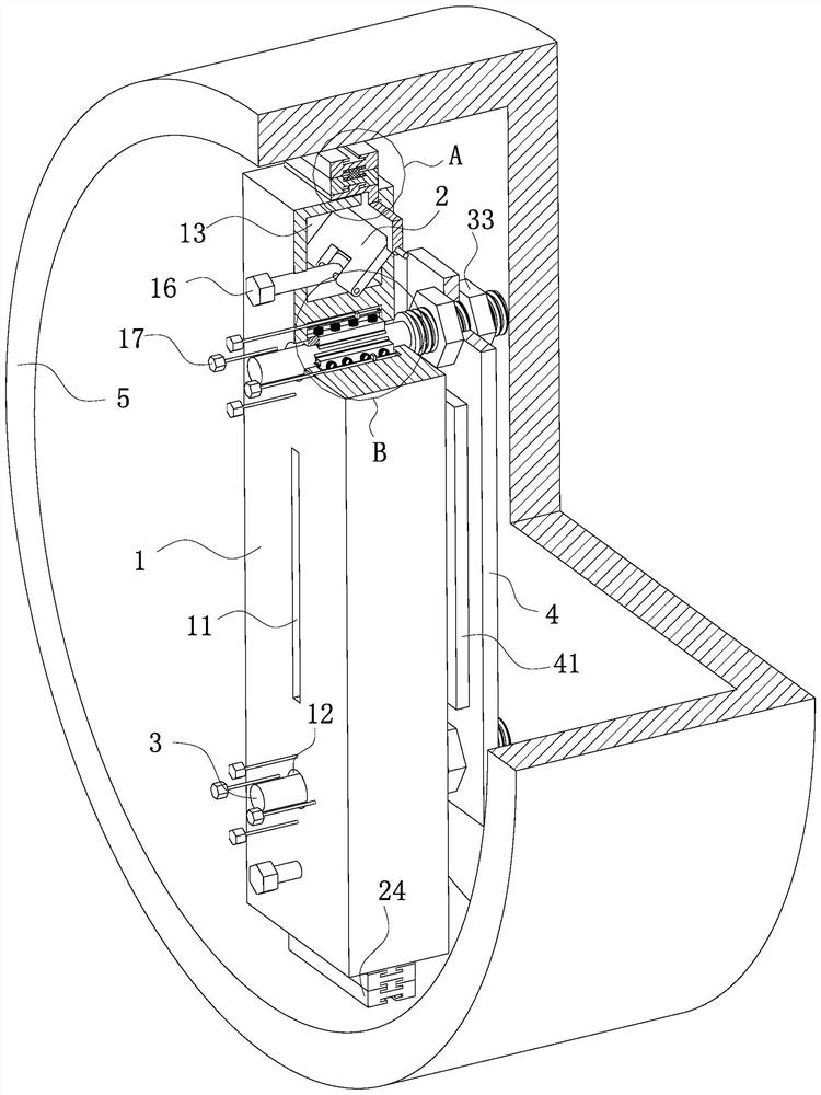
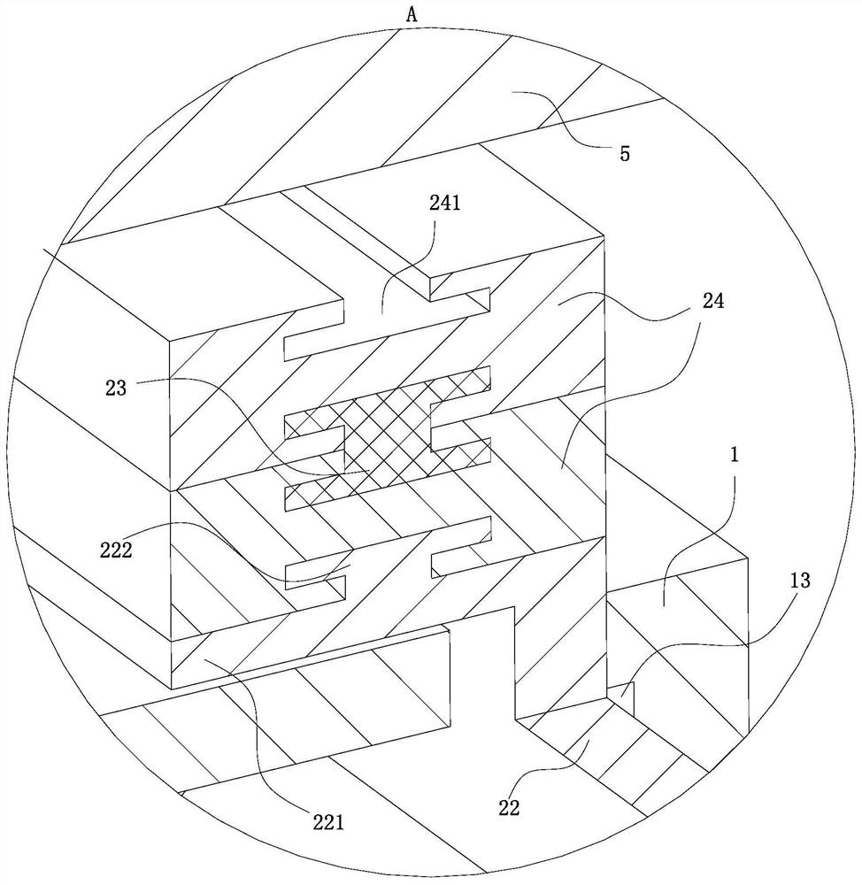
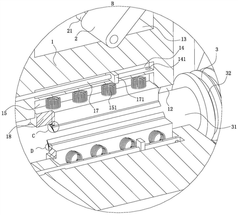
[0039]As an embodiment of the present invention, the first cavity 13 is opened in the auxiliary mounting plate 1; the distance between the first cavity 13 and the upper end face of the auxiliary mounting plate 1 in the length direction is smaller than that between the second cavity 14 and the second cavity. The distance between the upper end faces of the auxiliary mounting plate 1 in the length direction; the end face of the auxiliary mounting plate 1 is provided with a through hole; a telescopic plate 22 is slidably installed in the through hole; one end of the telescopic plate 22 is located Outside the cavity one 13, the other end stretches into the inside of the cavity one 13; on the end of the telescopic plate 22 outside the cavity one 13, a transverse plate 221 is fixedly installed; the transverse plate 221 and the auxiliary mounting plate 1 The end faces are parallel; the end of the telescopic plate 22 located in the cavity one 13 is hinged with a hinged plate 2; the end ...


PUM


Abstract

The invention belongs to the technical field of optical instruments, and specifically relates to an installation device and installation method for auxiliary adjustment of area array and line array detectors, including the following steps: S1: Fixing the PCB board (41) to the fixing frame (4) by glue ); S2: Fix the screw rod (3) on the fixed bracket (4) in the S1 step; S3: Insert the screw rod (3) into the perforation (12) on the basis of the S2 step, and pass the movable block (18 ) preliminarily fix the screw rod (3); S4: on the basis of step S3, place the auxiliary mounting plate (1) in the casing (5), rotate the fixing rod one (16), and squeeze the heightening block (24) to On the inner wall of the housing (5); S5: Based on the steps in S4, slowly rotate the fixing rod 2 (17) around the hole (12) on the auxiliary mounting plate (1), and adjust the position of the screw (3) accurately; S6: Complete After the fine adjustment of the fixing frame (4) in the step S5, the start-up test of the detector is carried out; the present invention has simple structure, is convenient to use, can reduce the difficulty of installing the detector and improve the installation accuracy.

Description

technical field [0001] The invention belongs to the technical field of optical instruments, in particular to an auxiliary adjustment surface array and linear array detector installation device and installation method. Background technique [0002] In existing optical instruments, photoelectric sensors are usually used to convert light into charges, and then realize the conversion of optical signals and digital signals, which is convenient for calculation and analysis of optical signals using computers. Therefore, photoelectric sensors are one of the important components of optical instruments. When installing a photoelectric sensor in an optical instrument, it is usually necessary to adjust the installation position of the photoelectric sensor several times to ensure that the installation position of the photoelectric sensor is correct and error-free, so that the photoelectric sensor can accurately receive the carried information incident on the optical instrument light and ...

Claims


Application Information

Patent Timeline
Patent Type & Authority Patents(China)
IPC IPC(8): G01D11/00F16B39/10
Inventor 聂荣志吴昌斌周淼淼彭波储涛熊泉赵子健张广维钟文婷
Owner 浙江澍源智能技术有限公司
Learn More