
Power distribution automation communication terminal card plugging device

A power distribution automation and plug-in device technology, applied to the parts, coupling devices, connections, etc. of the connection device, which can solve the problems of automatic disconnection, slow debugging progress, and poor contact between the communication terminal card and the module.

Active Publication Date: 2021-04-20
海南电网有限责任公司澄迈供电局
View PDF13 Cites 2 Cited by
  • Summary
  • Abstract
  • Description
  • Claims
  • Application Information

AI Technical Summary

Problems solved by technology

[0002] During the operation of power distribution automation equipment, it is often necessary to upload data to the cloud for processing. Generally, wireless data transmission is performed through an external communication terminal card. During the operation of existing power distribution automation equipment, the following problems often occur: 1. Many terminals in power distribution automation are frequently disconnected, which leads to the failure of the master station and dispatcher to collect information or remote control; 2. The reason for the poor contact of the communication card during the debugging process also makes the debugging progress slow, which greatly increases the debugging time. Burden; 3. Many devices that have been debugged are in the process of later operation, and because of the communication card slot is too large, the contact between the communication terminal card and the module is not good, and the connection will be automatically disconnected later, which is for debugging and later operation and maintenance. Increased burden and seriously affected the work efficiency of operation and maintenance personnel

Method used


Image

  • Power distribution automation communication terminal card plugging device
  • Power distribution automation communication terminal card plugging device
  • Power distribution automation communication terminal card plugging device

Examples


Embodiment Construction

[0021] In order to better understand the technical content of the present invention, a specific embodiment is provided below, and the present invention is further described in conjunction with the accompanying drawings.

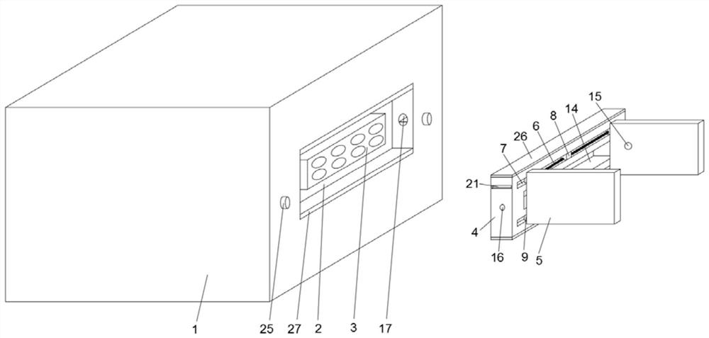
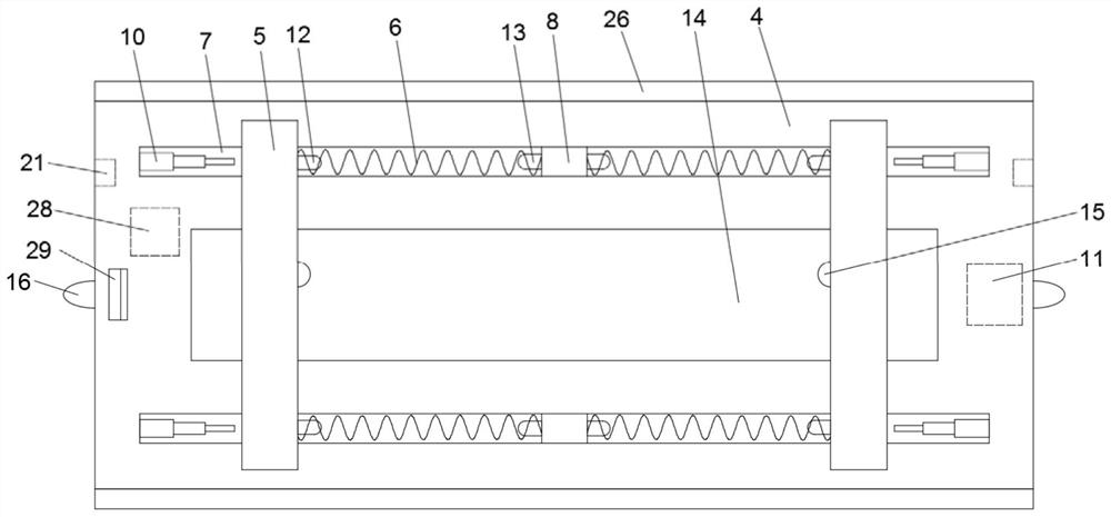
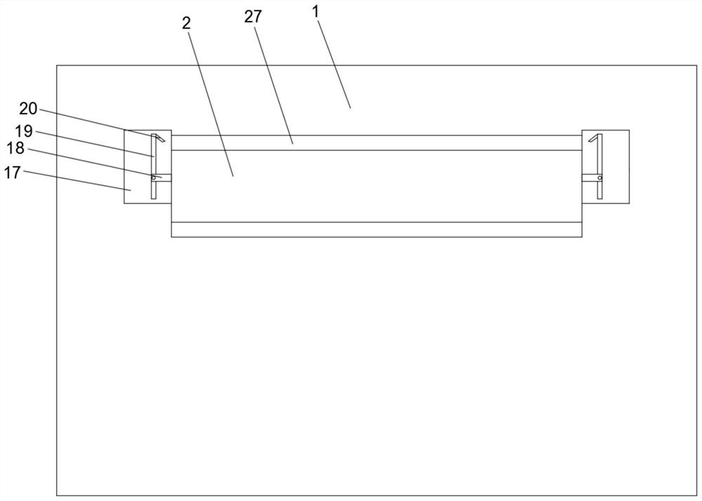
[0022] see Figure 1 to Figure 4 , a power distribution automation communication terminal card plug-in device provided by the present invention includes a power distribution terminal 1 and a ferrule for installing a communication terminal card, the outer surface of the power distribution terminal 1 is provided with a card slot 2, and the card The middle part of the groove 2 is provided with a communication female end 3, and the ferrule is inserted into the card groove 2 so that the communication terminal card is connected with the communication female end 3; the ferrule includes a plug plate 4, a clamping mechanism and a centering mechanism. The clamping mechanism includes a clamping plate 5 and a clamping spring 6, a chute 7 is provided on the side of the pl...


PUM


Abstract

The invention discloses a power distribution automation communication terminal card plugging device which comprises a power distribution terminal and a card sleeve, the card sleeve comprises a plugging plate, a clamping mechanism and a centering mechanism, the clamping mechanism comprises a clamping plate and a clamping spring, and the centering mechanism comprises an electric push rod, a controller, an infrared transmitting tube and an infrared receiving tube. A communication terminal card is clamped in the card sleeve, the card sleeve is inserted into the card slot of the power distribution terminal, the communication terminal card can be quickly inserted into the communication female end of the power distribution terminal, the arranged clamping mechanism can be suitable for clamping and fixing communication terminal cards of various sizes, the compatibility of the invention is improved, by arranging the centering mechanism, the position of the clamped communication terminal card can be adjusted, so that the communication terminal card is located in the center of the card sleeve, the communication terminal card can be accurately connected with the communication female end in an inserted mode when the card sleeve is connected with the power distribution terminal in an inserted mode, and the installation and insertion efficiency is improved.

Description

technical field [0001] The invention relates to the technical field of distribution network equipment, in particular to a distribution automation communication terminal card insertion device. Background technique [0002] During the operation of power distribution automation equipment, it is often necessary to upload data to the cloud for processing. Generally, wireless data transmission is performed through an external communication terminal card. During the operation of existing power distribution automation equipment, the following problems often occur: 1. Many terminals in power distribution automation are frequently disconnected, which leads to the failure of the master station and dispatcher to collect information or remote control; 2. The reason for the poor contact of the communication card during the debugging process also makes the debugging progress slow, which greatly increases the debugging time. Burden; 3. Many devices that have been debugged are in the process...

Claims


Application Information

Patent Timeline
IPC IPC(8): H01R13/639H01R13/631
Inventor 张翔伍人剑王荣王仁广杨恒威
Owner 海南电网有限责任公司澄迈供电局
Learn More