CT (computed tomography) machine operation and control device

A technology of control device and main control chip, which is applied in medical science, equipment for radiological diagnosis, diagnosis, etc. It can solve the problems of pulling the connecting hose, inconvenient use, and inconvenient observation of patients, so as to achieve flexible operation, convenient use, The effect of improving inspection efficiency

Inactive Publication Date: 2017-06-30
SAINUO WEISHENG SCI & TECH BEIJING
View PDF4 Cites 0 Cited by
  • Summary
  • Abstract
  • Description
  • Claims
  • Application Information

AI Technical Summary

Problems solved by technology

On the one hand, during daily operation, the doctor needs to operate the control panel close to the gantry to locate the patient’s position. When the patient is inside the gantry, it is very inconvenient to observe the actual position of the patient, especially in the process of enhanced CT examination, because the patient needs to The connecting hose is connected to the high-pressure injector next to the scanning frame. The connecting hose will interfere with the position of the doctor’s operation of the control panel, and even pull the connecting hose accidentally, causing the patient to need a second puncture accident.
Second, for some difficult cases or cases with complicated medical history, the CT examination method should be adjusted appropriately. Since it is not convenient to observe the patient's data during the scanning process, it is easy to miss relevant information and affect the comprehensiveness of the examination results if the conventional scanning method is used. Third, when CT machines are used in clinical applications such as biopsy and puncture positioning, doctors or technicians need to repeatedly determine the scanning range and locate the puncture needle path, and the fixed operation control panel is not flexible to operate in real time during the operation. It is extremely inconvenient to observe and adjust the position

Method used


Image

  • CT (computed tomography) machine operation and control device
  • CT (computed tomography) machine operation and control device
  • CT (computed tomography) machine operation and control device

Examples


Embodiment Construction

[0017] The present invention will be further described in detail below in conjunction with the accompanying drawings and embodiments.

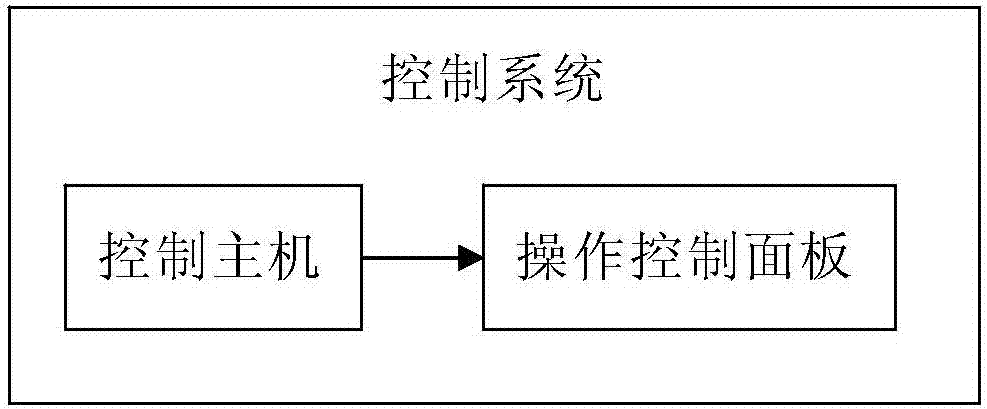
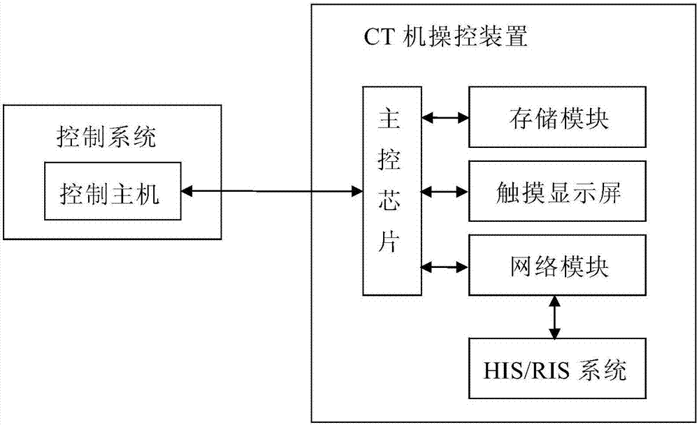
[0018] Such as figure 2 As shown, the CT machine control device disclosed in the present invention includes a box body, a main control chip, a storage module, and a network module in the box body, and a touch display screen is arranged on the box body, and a plurality of data input and output terminals of the main control chip are respectively connected to the The storage module, the network module, and the touch screen are connected, the main control chip establishes a data connection with the HIS / RIS system (hospital information system) through the network module, and the data input and output terminals of the control host of the CT machine control system communicate with the main control unit The data input and output terminals of the chip are connected.

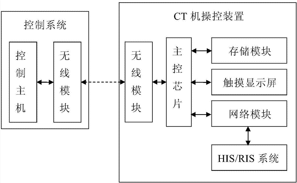
[0019] Such as image 3 As shown, in another embodiment, the CT machine and the CT...


PUM


Abstract

The invention provides a CT (computed tomography) machine operation and control device, which comprises a box body, wherein a main control chip, a storage module and a network module are arranged in the box body; a touch display screen is arranged on the box body; the corresponding data input and output end of the main control chip is respectively connected with the storage module and the touch display screen; the main control chip builds data connection with an HIS(hospital information system) / RIS (radiology information system) through a network module; the data input and output end of the main control chip is connected with the data input and output end of a control host of a CT machine. Patient information data in the HIS / RIS is transmitted to the CT machine operation and control device through networks; the patient information is displayed through the touch display screen; scanning parameters are input through the touch display screen according to the patient information and the patient position; the patient parameters and the scanning parameters are transmitted to the control host; the control host controls the CT machine to act according to the received patient parameters and the scanning parameters. The CT machine operation and control device has the advantages that the operation is flexible; the use is convenient.

Description

technical field [0001] The invention relates to a CT machine control device, in particular to a CT machine control device which can remotely receive scanning information of a patient and can moveably control the CT machine. Background technique [0002] Existing CT machines are generally equipped with operation control panels at the front and rear positions of the scanning frame, which are used to adjust the position of the scanning bed, adjust the scanning mode and range, input patient information, control start / stop, etc. [0003] Fixed-setting operator control panels have major limitations. On the one hand, during daily operation, the doctor needs to operate the control panel close to the gantry to locate the patient’s position. When the patient is inside the gantry, it is very inconvenient to observe the actual position of the patient, especially in the process of enhanced CT examination, because the patient needs to The connecting hose is connected to the high-pressure...

Claims


Application Information

Patent Timeline
Patent Type & Authority Applications(China)
IPC IPC(8): A61B6/03
CPCA61B6/46A61B6/03A61B6/548
Inventor 徐晓磊
Owner SAINUO WEISHENG SCI & TECH BEIJING
Why Eureka
Try Eureka