
Power distribution cabinet structure convenient for emergency power supply

A technology for emergency power supply and power distribution cabinets, which is applied in substation/power distribution device housings, electrical components, climate change adaptation, etc. It can solve problems such as loose connections, large pulling forces, and entangled wires and cables in power distribution cabinets. To achieve the effect of reducing the looseness of the connection, meeting the needs of use, and improving the utilization rate

Active Publication Date: 2021-04-20
佛山祥电电力设计工程有限公司
View PDF7 Cites 3 Cited by
  • Summary
  • Abstract
  • Description
  • Claims
  • Application Information

AI Technical Summary

Problems solved by technology

[0003] Most of the existing power distribution cabinets are connected with many wires and cables for the control of different circuits, and the wires and cables are extended to the outside of the power distribution cabinet to connect and supply power to external circuits, but the existing power distribution cabinets do not have the ability to The wires and cables are arranged and pressed together, and the wires and cables in the power distribution cabinet are often entangled and become messy, which makes it difficult for people to quickly wire for emergency power supply operations. The large pulling force causes the connection to be loose, which cannot meet the needs of use. Therefore, we propose a power distribution cabinet structure that is convenient for emergency power supply to solve the above problems

Method used


Image

  • Power distribution cabinet structure convenient for emergency power supply
  • Power distribution cabinet structure convenient for emergency power supply
  • Power distribution cabinet structure convenient for emergency power supply

Examples


Embodiment

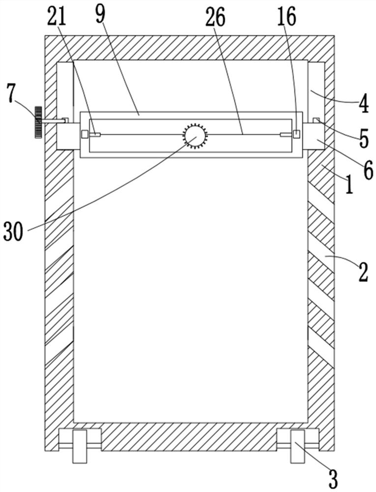
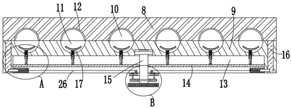
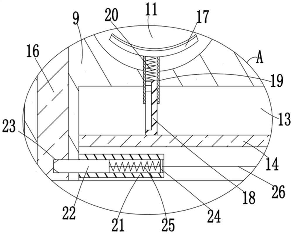
[0027] refer to Figure 1-5, this embodiment proposes a power distribution cabinet structure that is convenient for emergency power supply, including a power distribution cabinet body 1, and a plurality of inclined downward cooling holes 2 are opened on the inner walls of both sides of the power distribution cabinet body 1, The bottom of the box body 1 of the power distribution cabinet is rotatably equipped with four traveling wheels 3, and the inner walls on both sides of the box body 1 of the power distribution cabinet are provided with a first groove 4 with an opening on the front side, and on the bottom inner wall of the first groove 4 The first positioning rod 5 is fixedly installed, and the sliding sleeve on the first positioning rod 5 is provided with a moving block 6. Among the two moving blocks 6, the top of the moving block 6 on the left side is in movable contact with a T-shaped quick-fixing bolt 7, and the T-shaped The left side of the fast-fixing bolt 7 extends to...


PUM


Abstract

The invention provides a power distribution cabinet structure convenient for emergency power supply. The power distribution cabinet structure comprises a power distribution cabinet box body, the inner walls of the two sides of the power distribution cabinet box body are both equipped with a plurality of inclined downward heat dissipation holes, the bottom of the power distribution cabinet box body is rotatably equipped with four walking wheels, first grooves with openings in the front sides are formed in the inner walls of the two sides of the power distribution cabinet box body, first positioning rods are fixedly installed on the inner walls of the bottoms of the first grooves, and the first positioning rods are sleeved with moving blocks in a sliding mode. The power distribution cabinet structure is reasonable in design, facilitates orderly arrangement and fixation of wires and cables, facilitates wiring operation of personnel during emergency power supply operation, can reduce the phenomenon of joint loosening caused by pulling force, and can press and fix the wires and cables of different thicknesses at the same time through cooperation with a first spring; a wire arrangement mechanism can be taken out and fixed in another power distribution cabinet box body for use, the utilization rate is improved, and the use requirements are met.

Description

technical field [0001] The invention relates to the technical field of power distribution cabinet structures, in particular to a power distribution cabinet structure that facilitates emergency power supply. Background technique [0002] The power distribution cabinet is the collective name of the motor control center. It is mainly divided into power distribution cabinets, lighting distribution cabinets, and metering cabinets. It is the final equipment of the power distribution system. They distribute the electric energy of a certain circuit of the upper-level power distribution equipment to the nearby loads, and the power distribution cabinets are mainly used for emergency power supply places when in use. Move to the site for power supply work; [0003] Most of the existing power distribution cabinets are connected with many wires and cables for the control of different circuits, and the wires and cables are extended to the outside of the power distribution cabinet to conne...

Claims


Application Information

Patent Timeline
Patent Type & Authority Applications(China)
IPC IPC(8): H02B1/30H02B1/20H02G3/04H02G3/16
CPCY02A30/14
Inventor 梁辉平陆俊强李铭基蒋宁汤锦洪谢智斌刘昕罗杰青周京旸李分先何国盛郑怀好郑胜航罗宇健劳笑华朱国忠郑超宇曾宪业王真真袁明石李新龙李咏梅
Owner 佛山祥电电力设计工程有限公司
Learn More