Charging method, electronic device and storage medium
A charging method and charging current technology, applied in battery circuit devices, circuit devices, secondary battery charging/discharging, etc., can solve the problems of prolonged constant voltage charging, long total battery charging time, shortening constant current charging time, etc. problem, achieve the effect of shortening the full charging time, shortening the constant voltage charging time, and improving the constant current charging time
- Summary
- Abstract
- Description
- Claims
- Application Information
AI Technical Summary
Problems solved by technology
Method used
Image
Examples
Embodiment 1
[0137] (1) Parameter U m set up
[0138] U during battery cycling m Change according to the following rules:
[0139] u m =U cl +b 1 ×m+b 2 , where U cl=4.45V, U cl is the cut-off voltage of the battery at the end of the constant current charging phase in the first charge-discharge cycle, 1≤m≤80, b 1 =0,b 2 =0; 81≤m≤500, b 1 =0.0002,b 2 =0.
[0140] (2) Charging process
[0141] Ambient temperature: 25°C;
[0142] Charging process:
[0143] Step 1: Obtain the current actual capacity Q of the battery;
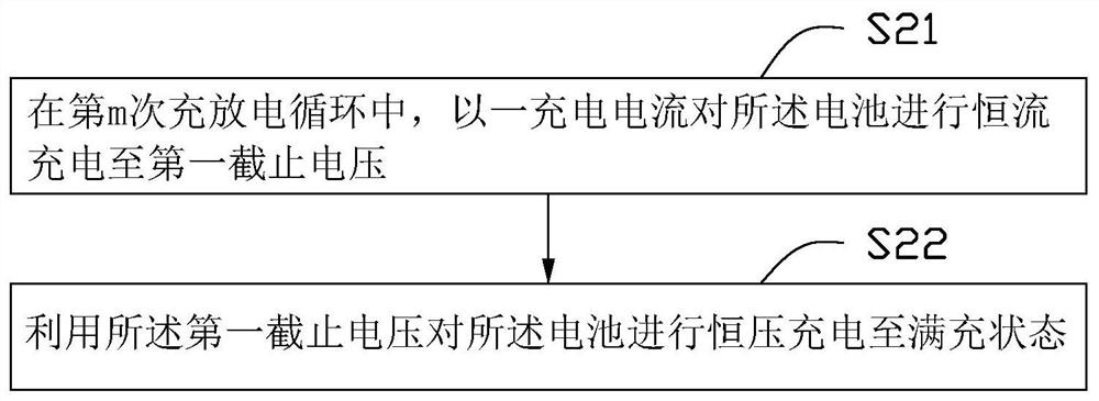
[0144] Step 2: Use a constant current of 1.5C to charge the battery until the voltage of the battery reaches the cut-off voltage U m , U m Change with the number of cycles m according to the preset formula;
[0145] Step 3: Continue to use U m Charge the battery with a constant voltage until the total capacity of the battery is Q;
[0146] Step 4: Let the battery stand for 5 minutes;
[0147] Step 5: Discharge the battery with a constant current of 1.0C unti...
Embodiment 2
[0151] (1) Parameter U m set up
[0152] U during battery cycling m Change according to the following rules:
[0153] u m =U cl +b 1 ×m+b 2 , where U cl =4.45V, 1≤m≤80, b 1 =0,b 2 =0; 81≤m≤500, b 1 =0.0001,b 2 = 0.01.
[0154] (2) Charging process
[0155] Same as Example 1, except that the U set in Example 2 is used m .
Embodiment 3
[0157] (1) Parameter U m set up
[0158] U during battery cycling m Change according to the following rules:
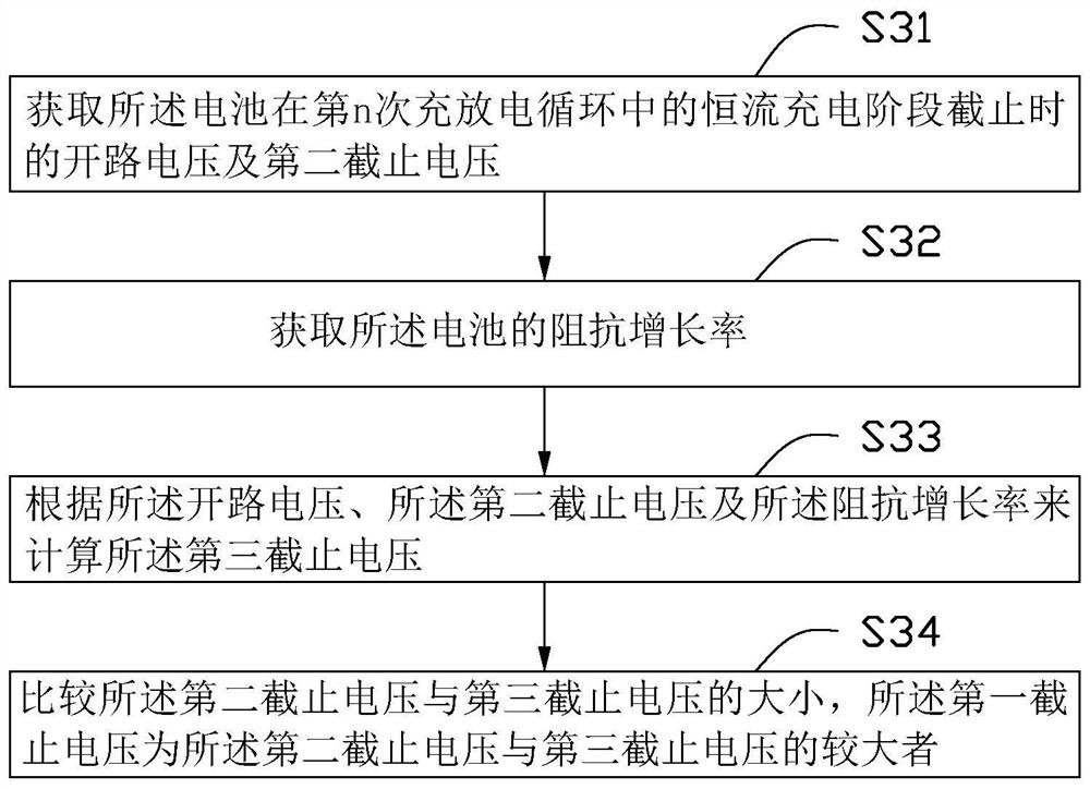
[0159] In each loop, U m Take U and U cl The one with the larger value, where U=OCV 1 +(U cl -OCV 1 ) × k, U cl =4.45V, OCV 1 =4.10V, U cl and OCV 1 are the cut-off voltage and open-circuit voltage of the battery at the end of the constant current charging phase in the first charge-discharge cycle, and k is the impedance growth rate of the battery. It is necessary to collect the actual impedance of the battery at any time during the battery cycle and calculate the growth rate rate, k=R 2 / R 1 , R 2 is the battery impedance when SOC=50% in the m-1th charging process of the battery, R 1 It is the battery impedance when SOC=50% in the first charging process of the battery, and the value is R 1 =60mOhm;
[0160] (2) Charging process
[0161] Same as Example 1, except that the U set in Example 3 is used m .
PUM
 Abstract
Description
Claims
Application Information
 - R&D
- Intellectual Property
- Life Sciences
- Materials
- Tech Scout
- Unparalleled Data Quality
- Higher Quality Content
- 60% Fewer Hallucinations
Browse by: Latest US Patents, China's latest patents, Technical Efficacy Thesaurus, Application Domain, Technology Topic, Popular Technical Reports.
© 2025 PatSnap. All rights reserved.Legal|Privacy policy|Modern Slavery Act Transparency Statement|Sitemap|About US| Contact US: help@patsnap.com


