

A control method and terminal for parallel charging
A charging control and terminal technology, applied in the direction of secondary battery charging/discharging, charging/discharging current/voltage regulation, current collector, etc., can solve the problems of long charging time, terminal charging heat, slow charging speed, etc., to achieve charging speed Fast, reduce the terminal temperature, avoid the effect of charging heat
- Summary
- Abstract
- Description
- Claims
- Application Information
AI Technical Summary
Problems solved by technology
Method used
Image

Examples
Embodiment 1
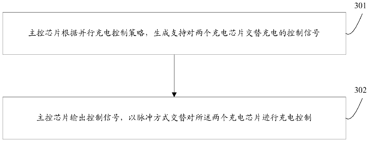
[0084] The control method of parallel charging in the embodiment of the present invention, such as image 3 shown, including the following steps:
[0085] Step 301, the main control chip generates a control signal supporting alternate charging of the two charging chips according to the parallel charging control strategy.
[0086] Step 302 , the main control chip outputs a control signal to control the charging of the two charging chips alternately in a pulse manner.
[0087] Adopting the embodiment of the present invention, it is not a complete constant current charging, after four stages of trickle charging state-constant current charging state-constant voltage charging state-charging completion state, and the control is in the constant current charging state within a predetermined time, there will be Relatively large current, in this way, the constant current charging time is prolonged, so that the constant current time will not soon reach the constant voltage charging stat...
Embodiment 2
[0089] The control method of parallel charging in the embodiment of the present invention, such as Figure 4 shown, including the following steps:
[0090] Step 401, the main control chip generates a control signal supporting alternate charging of the two charging chips according to the parallel charging control strategy.
[0091] Step 402, the main control chip reads the terminal battery voltage Vb, judges whether Vb>V1, and obtains a judgment result; wherein, V1 is the critical point voltage from the trickle charging state to the constant current charging state.
[0092] Step 403 , when the judgment result is Vb>V1, the constant current charging condition is satisfied, then output the control signal, start the pulse charging in the constant current stage, and control the charging of the two charging chips alternately.
[0093] Adopting the embodiment of the present invention, it is not a complete constant current charging, after four stages of trickle charging state-constan...
Embodiment 3
[0095] The control method of parallel charging in the embodiment of the present invention, such as Figure 5 shown, including the following steps:
[0096] Step 501, the main control chip generates a control signal supporting alternate charging of the two charging chips according to the parallel charging control strategy.
[0097]Step 502, the main control chip reads the terminal battery voltage Vb, judges whether Vb>V1, and obtains a judgment result; wherein, V1 is the critical point voltage from the trickle charging state to the constant current charging state.
[0098] Step 503 , when the judgment result is Vb>V1, the constant current charging condition is met, then output the control signal, start the pulse charging in the constant current stage, and control the charging of the two charging chips alternately.
[0099] Step 504: output the first control signal to enable the first charging chip, set the charging current for the first charging chip to I1, and the charging ti...
PUM
 Abstract
Description
Claims
Application Information