
A fire-proof and explosion-proof floating plate and fire-proof method

A technology of floating discs and sealing discs, which is applied in the field of fire-proof and explosion-proof floating discs and fire protection, and can solve problems such as increased costs, inability to detect oil storage tanks, and large probe limitations

Active Publication Date: 2021-06-25
上原石化设备(常州)有限公司
View PDF6 Cites 0 Cited by
  • Summary
  • Abstract
  • Description
  • Claims
  • Application Information

AI Technical Summary

Problems solved by technology

[0003] However, the probe has relatively large limitations. When the probe is damaged and not replaced in time, the oil storage tank cannot be detected. At the same time, the replacement of the probe will undoubtedly increase the cost

Method used


Image

  • A fire-proof and explosion-proof floating plate and fire-proof method
  • A fire-proof and explosion-proof floating plate and fire-proof method
  • A fire-proof and explosion-proof floating plate and fire-proof method

Examples


Embodiment 1

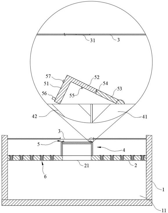
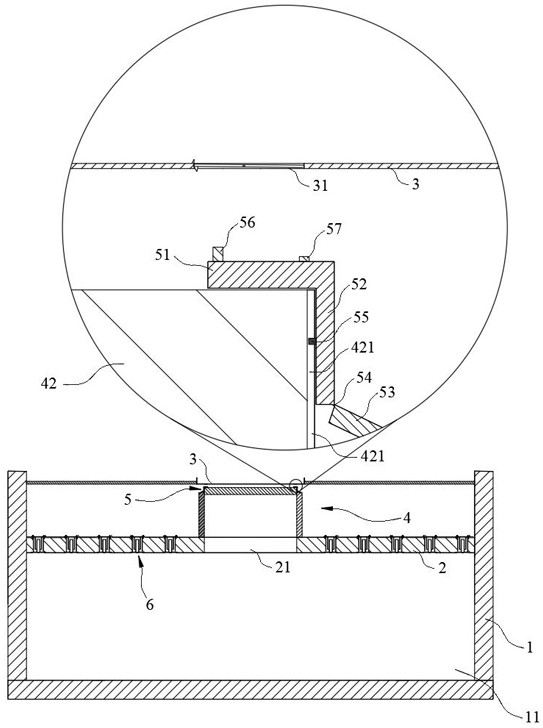
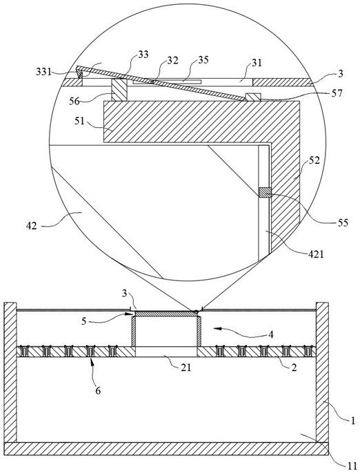
[0029] The traditional storage tank includes a storage tank body 1 and a floating plate body 2 slidingly connected in the storage tank body 1, and a storage tank suitable for filling oil is formed between the storage tank body 1 and the floating plate body 2. The oil cavity 11, through the discharge of the oil in the oil storage cavity 11, makes the floating plate body 2 go up and down, and the floating plate body 2 plays a role in reducing the volatilization loss of the oil in the oil storage cavity 11 As a result, it is usually required that the floating disc body 2 and the inner side wall of the storage tank body 1 be in close contact, so as to realize the sealing between the floating disc body 2 and the inner side wall of the storage tank body 1, and such a design is when the oil storage cavity 11 When an explosion occurs, the entire floating plate body 2 will be damaged due to the seal between the floating plate body 2 and the inner wall of the storage tank body 1. At the ...

Embodiment 2

[0046] On the basis of the first embodiment, the second embodiment also provides a fire prevention method for the fireproof and explosion-proof floating tray, wherein the structure of the fireproof and explosion-proof floating tray is the same as that of the first embodiment, and will not be repeated here.

[0047]Specifically, when the pressure in the oil storage cavity 11 increases, the sealing disc 42 is pushed up; the upper blocking piece 51 is pushed up by the sealing disc 42 until the upper blocking piece 51 is attached to the upper end surface of the sealing disc 42 and the middle blocking piece 52 Fit the outer wall of the sealing disc 42 so that the upper stopper 51 blocks the sealing disc 42 from coming out of the sealing sleeve 41; when the pressure in the oil storage cavity 11 continues to increase to exceed the maximum stress of the crease 54, the crease 54 breaks off, and the upper blocking piece 51 continues to be pushed by the sealing disc 42; when the upper blo...


PUM


Abstract

The invention relates to the technical field of storage tank floating plates, in particular to a fire-proof and explosion-proof floating plate and a fire-proof method. One of the fire-proof and explosion-proof floating discs includes a liquid storage pool fixed at the top center of the storage tank body and a sealing structure arranged at the top center of the floating disc body; and a number of stoppers are hinged on the edge of the top surface of the sealing structure, and the stoppers are inverted Buckled on the top surface of the sealing structure, the stopper is in point contact with the top surface of the sealing structure; an oil storage cavity suitable for filling oil is formed between the storage tank body and the floating plate body; when the pressure in the oil storage cavity increases , the sealing structure can lift up the stopper until the stopper is in surface-to-surface contact with the top end of the sealing structure; after the stopper is lifted up until broken, the stopper can extend into the liquid storage pool to allow the cooling liquid to flow out. Through the setting of the stopper, it plays an explosion-proof role when the pressure in the oil storage cavity is low, and it plays the role of opening the liquid storage tank to cool the oil storage cavity when the pressure in the oil storage cavity is high, and at the same time, it can also cool the outflowing coolant. play a guiding role.

Description

technical field [0001] The invention relates to the technical field of storage tank floating plates, in particular to a fire-proof and explosion-proof floating plate and a fire-proof method. Background technique [0002] At present, the fire-fighting measures for oil storage tanks widely used are to establish a fire-fighting system in the tank area and install a probe on the upper part of the tank. After the tank is on fire, the probe is activated and the signal is transmitted to the foaming station. A large amount of foam is sprayed into the tank through the delivery pipe. , put out the fire. [0003] However, the probe has relatively large limitations. When the probe is damaged and not replaced in time, the oil storage tank cannot be tested. At the same time, the replacement of the probe will undoubtedly increase the cost. Contents of the invention [0004] In order to solve the above technical problems, the present invention provides a fire-proof and explosion-proof fl...

Claims


Application Information

Patent Timeline
Patent Type & Authority Patents(China)
IPC IPC(8): B65D90/32B65D88/42
CPCB65D88/42B65D90/325
Inventor 苏进发张倜哲
Owner 上原石化设备(常州)有限公司
Learn More