

Bus frame with temperature monitoring function
A technology of busbar frame and function, which is applied in the direction of busbar installation, cooling busbar device, fully enclosed busbar device, etc. It can solve the problems of busbar frame fire, space temperature rise, simple structure, etc., and achieve the effect of quick disassembly and cleaning
- Summary
- Abstract
- Description
- Claims
- Application Information
AI Technical Summary
Problems solved by technology
Method used
Image

Examples
Embodiment 1
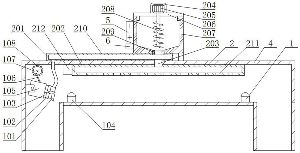
[0026] see Figure 1-6 , the present invention provides a technical solution:
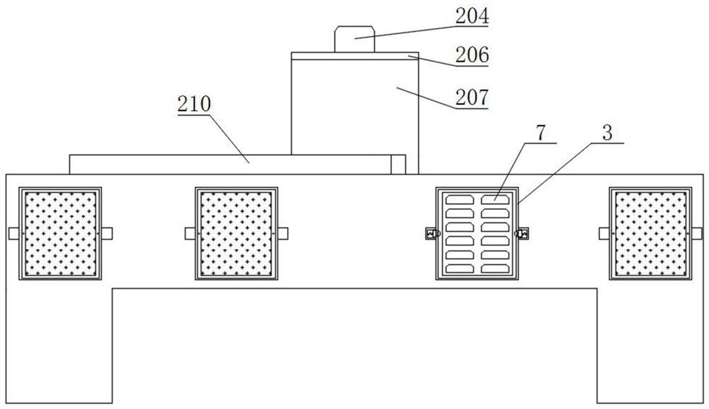
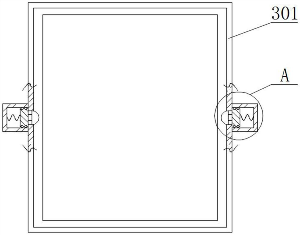
[0027] A bus frame with temperature monitoring function, comprising a bus frame body 4 and a battery 5, characterized in that: a temporary fire extinguishing device 2 is fixedly connected to the top of the bus frame body 4, and a temporary fire extinguishing device 2 is fixedly connected to a left end of the temporary fire extinguishing device 2 The battery 5 and the controller 6, and the controller 6 is arranged on the lower side of the battery 5, the temperature monitoring and control device 1 is fixedly connected to the inner side of the left end of the busbar frame main body 4, and the front and rear ends of the busbar frame main body 4 are provided with There is a ventilation hole 7, and one side of the ventilation hole 7 is fixedly connected with a dust blocking device 3, and the dust blocking device 3 is fixedly connected with the main body 4 of the busbar frame, and the temperature monitori...
Embodiment 2
[0030] The same parts of Embodiment 2 and Embodiment 1 will not be described in detail. The difference is that when the smoke alarm 212 detects a fire on the inside of the main body 4 of the busbar frame, the smoke alarm 212 controls the solenoid valve 102 on the lower side to close through the controller 6. The electromagnetic valve 102 on the upper side is opened, and the blower fan 105 also starts working simultaneously, and the controller 6 controls the second motor 205 to drive the conveying screw 208 to rotate on the inside of the material storage box 207, and the material storage box 207 is conveniently unloaded by the conveying screw 208. The gas that runs out from blower fan 105 is ejected through the second air outlet pipe 201, air inlet pipe 210, discharge pipe 203, spray powder shell 202 and material injection port 211, and the gas will generate negative pressure at the outlet of material guide pipe 209 simultaneously, The dry powder inside the material storage box ...
PUM
 Abstract
Description
Claims
Application Information