Light workpiece grabbing device for machining

A grasping device and machining technology, applied in the field of machining, can solve the problems of many linkage mechanisms of the grasping device and complicated grasping devices, etc.

Inactive Publication Date: 2021-04-23
XIJING UNIV
View PDF0 Cites 2 Cited by
  • Summary
  • Abstract
  • Description
  • Claims
  • Application Information

AI Technical Summary

Problems solved by technology

[0002] During mechanical processing, light workpiece is one of many workpieces. When processing light workpieces, grabbing devices are needed to adjust the position of light workpieces. However, there are many linkage mechanisms of existing grabbing devices, which leads to the complex device

Method used


Image

  • Light workpiece grabbing device for machining
  • Light workpiece grabbing device for machining
  • Light workpiece grabbing device for machining

Examples


Embodiment 1

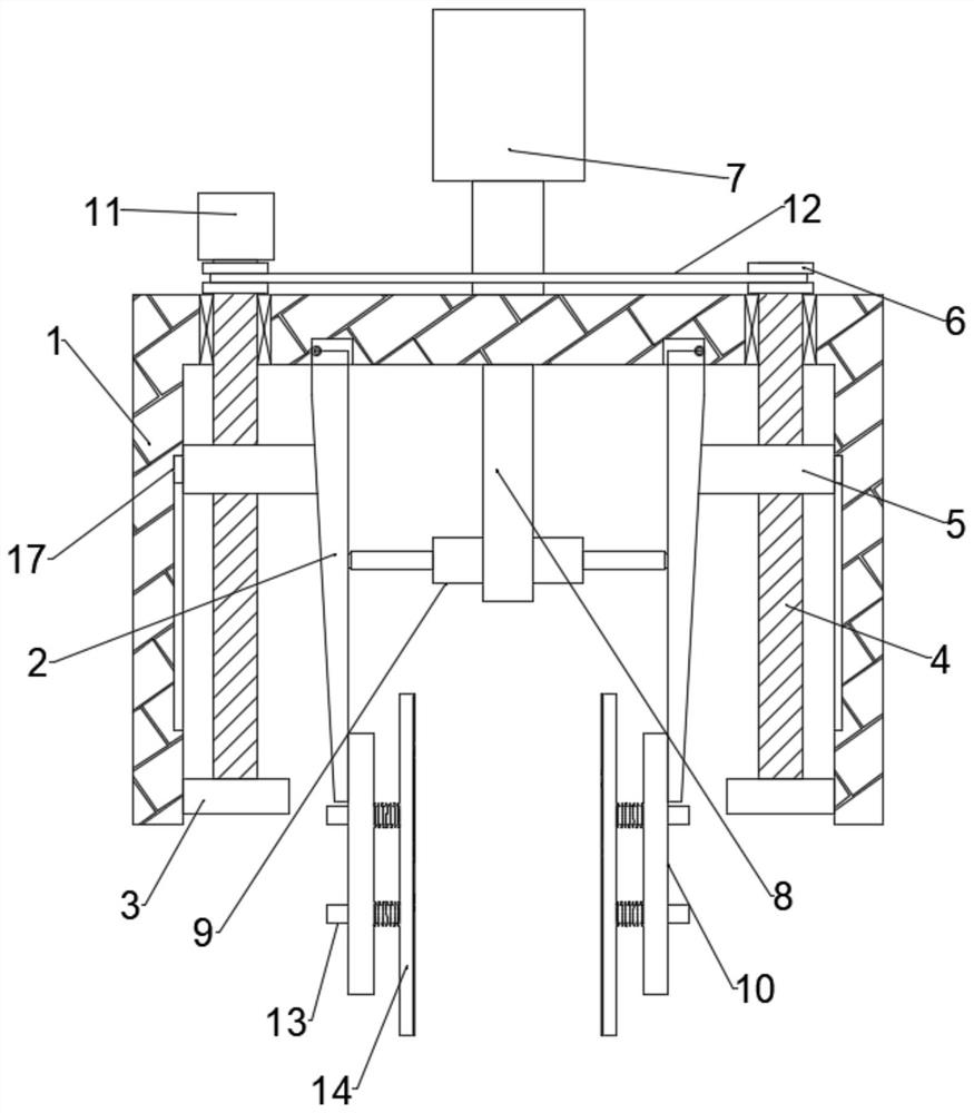
[0022] combine Figure 1-4 , a light-duty workpiece grabbing device for mechanical processing, comprising an electric push rod 7, a mounting frame 1 is installed on the movable end of the electric push rod 7, and two wedge-shaped plates 2 are connected to the inside of the mounting frame 1 for rotation, and The two wedge-shaped plates 2 are arranged symmetrically about the center of the mounting frame 1, and a threaded rod 4 is arranged between the two wedge-shaped plates 2 and the inner wall of the mounting frame 1, and one end of the threaded rod 4 is fixed to the mounting frame. The fixed plate 3 on 1 is connected by rotation, and the other end is connected with the driving mechanism through the upper end of the installation frame 1. The threaded rod 4 is threaded with a threaded block 5, and one end of the threaded block 5 slides with the inner wall of the installation frame 1. connection, the other end is in contact with the slope of the wedge-shaped plate 2, and the midd...

Embodiment 2

[0031] combine Figure 1-2 , a light-duty workpiece grabbing device for mechanical processing. This embodiment further limits the invention on the basis of Embodiment 1.

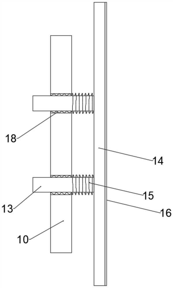
[0032] A plurality of connecting rods 13 all pass through the mounting plate 10 and are slidably connected with the mounting plate 10. A second spring 15 sleeved on the outside of the connecting rod 13 is connected between the mounting plate 10 and the splint 14. 13 all run through the mounting plate 10 and are slidably connected with the mounting plate 10, so that the second spring 15 can be used to achieve buffering when grabbing, and avoid damage to light workpieces caused by large clamping forces.

[0033] The mounting plate 10 and the outer side of the connecting rod 13 are all embedded with a sliding sleeve 18, and the connecting rod 13 is slidably connected with the sliding sleeve 18. The sliding connection between the connecting rod 13 and the sliding sleeve 18 facilitates the smooth and stable opera...


PUM


Abstract

The invention discloses a light workpiece grabbing device for machining. The light workpiece grabbing device comprises an electric push rod, wherein a mounting frame is mounted at the movable end of the electric push rod; two wedge-shaped plates are rotationally connected to the interior of the mounting frame and are symmetrically arranged about the center of the mounting frame; and a threaded rod is arranged between each of the two wedge-shaped plates and the inner wall of the mounting frame. According to the light workpiece grabbing device, the two threaded rods are simultaneously driven to rotate forwards through a driving mechanism, one end of each threaded block is in sliding connection with the inner wall of the mounting frame cooperatively, and the other end of each threaded block is in contact with the inclined surface of the corresponding wedge-shaped plate, so that the threaded rods rotate to drive the threaded blocks to move simultaneously, the two threaded blocks move and push the two wedge-shaped plates to rotate, two clamping plates are driven to get close to each other through a mounting plate and a connecting rod, and a light workpiece is grabbed through the two clamping plates; and the light workpiece can be put down through cooperation with a reset mechanism, and thus, the circumstance that an existing grabbing device has a plurality of linkage mechanisms, and the whole grabbing device is complex in structure is avoided.

Description

technical field [0001] The invention relates to the technical field of mechanical processing, in particular to a light-duty workpiece grasping device for mechanical processing. Background technique [0002] During mechanical processing, light workpiece is one of many workpieces. When processing light workpieces, grabbing devices are needed to adjust the position of light workpieces. However, there are many linkage mechanisms of existing grabbing devices, which leads to the The device is complicated. Therefore, a light-duty workpiece grabbing device for mechanical processing is proposed to solve the above problems. Contents of the invention [0003] The object of the present invention is to provide a light-duty workpiece grabbing device for mechanical processing, so as to solve the problems raised in the above-mentioned background technology. [0004] To achieve the above object, the present invention provides the following technical solutions: [0005] A light-duty work...

Claims


Application Information

Patent Timeline
Patent Type & Authority Applications(China)
IPC IPC(8): B65G47/90
CPCB65G47/90
Inventor 黄建社乔勋金作勇薛少钧蒲学文
Owner XIJING UNIV
Why Eureka
Try Eureka