
Three-shaft horizontal rotary full-automatic take-up device

A wire take-up device, fully automatic technology, applied in the direction of transportation and packaging, transportation of filamentous materials, thin material processing, etc., can solve the precision requirements of spare parts that do not meet the requirements, the success rate of enameled wire replacement is low, waste, etc. problems, to achieve the effect of improving automation, simple structure, and low cost of mass production

Pending Publication Date: 2021-04-23
佛山市顺德区盛永机械有限公司
View PDF0 Cites 4 Cited by
  • Summary
  • Abstract
  • Description
  • Claims
  • Application Information

AI Technical Summary

Problems solved by technology

This method of operation makes the part of the enameled wire (called the bottom line in the industry) that is stuck together with the double-sided tape at the bottom of the wire reel unusable, thus causing waste
[0004] Although there are very few small-size enamelling machines that use automatic disc changing devices (such as the Japanese Jiuyuan enamelling machine), at present, only a small number of large-size enameled wire equipment in China have automatic disc-changing devices, and small-size enamelling machines use The fully automatic disk changing device is basically blank
The main reason is that the precision requirements of domestically manufactured spare parts cannot meet the requirements, resulting in a lower success rate of changing enameled wires with smaller specifications.

Method used


Image

  • Three-shaft horizontal rotary full-automatic take-up device
  • Three-shaft horizontal rotary full-automatic take-up device

Examples


Embodiment Construction

[0019] Certain terms are used, for example, in the description and claims to refer to particular components. Those skilled in the art should understand that hardware manufacturers may use different terms to refer to the same component. The specification and claims do not use the difference in name as a way to distinguish components, but use the difference in function of components as a criterion for distinguishing. As mentioned throughout the specification and claims, "comprising" is an open term, so it should be interpreted as "including but not limited to". "Approximately" means that within an acceptable error range, those skilled in the art can solve the technical problem within a certain error range and basically achieve the technical effect.

[0020] In the description of the present invention, it should be understood that the orientation or positional relationship indicated by the terms "upper", "lower", "front", "rear", "left", "right", horizontal" etc. are based on th...


PUM


Abstract

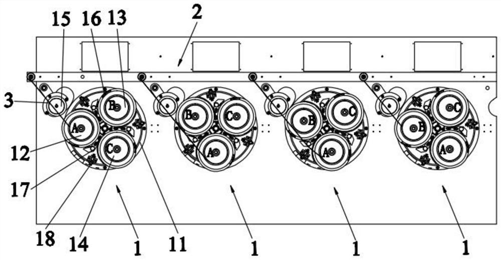
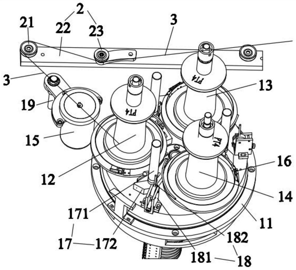
The invention relates to the technical field of take-up equipment, and specifically relates to a three-shaft horizontal rotary full-automatic take-up device comprising at least one reel changing mechanism and wire arranging mechanisms corresponding to the reel changing mechanisms. Each reel changing mechanism comprises a rotary disc, a take-up reel A, a take-up reel B, a take-up reel C and a synchronous motor, and each take-up reel A, the corresponding take-up reel B and the corresponding take-up reel C are arranged on the corresponding rotary disc in a triangular structure. Wire clamping devices are arranged on the circumferential edges of the take-up reels A, the take-up reels B and the take-up reels C correspondingly, a wire cutting mechanism is arranged between every two adjacent take-up reels of each take-up reel A, the corresponding take-up reel B and the corresponding take-up reel C, a wire shifting mechanism is arranged on the edge, corresponding to the corresponding wire cutting mechanism, of each rotary disc, and each synchronous motor is arranged on one side of the corresponding rotary disc. Each wire arranging mechanism is provided with at least one wire arranging wheel, and each wire arranging wheel obliquely corresponds to one rotary disc. The take-up reels A, the take-up reels B and the take-up reels C cooperate with one another, automatic reel changing of automatic take-up is achieved, the take-up efficiency is improved, the structure is simple, and the mass production cost is lower.

Description

technical field [0001] The invention relates to the technical field of wire take-up equipment, in particular to a three-axis horizontal rotating fully automatic wire take-up device. Background technique [0002] In the existing enameled wire industry, semi-automatic reel changing devices are generally used when small-sized enameled wires are rewound. When switching reels, double-sided adhesive tape needs to be wound around the bottom of the empty reel and glued with double-sided adhesive tape. After holding the enameled wire, use a waxed paper strip to separate the enameled wire stuck by the double-sided tape, and finally continue to wind until it is full. Such an operation mode will inevitably produce the enameled wire at the bottom of the coil with the double-sided tape sticking together. [0003] However, users of enameled wire have always had great opinions on the waste caused by the residue of the bottom wire at the bottom of the small-sized enameled wire reel. But at...

Claims


Application Information

Patent Timeline
Patent Type & Authority Applications(China)
IPC IPC(8): B65H54/44B65H54/20B65H67/048B65H54/70B65H57/14B65H54/28
CPCB65H54/44B65H54/20B65H54/205B65H67/048B65H54/70B65H57/14B65H54/2818B65H2701/36
Inventor 戴维
Owner 佛山市顺德区盛永机械有限公司
Learn More