
Moisture-proof dehumidification device for electric appliance cabinet

A technology of electrical cabinets and resistors, which is applied to the installation of electrical equipment shells/cabinets/drawers, electrical components, and support structures, etc. It can solve problems such as damp, short-circuit fires, and no dehumidification and drying of electronic components, so as to reduce costs and prolong service life. , Reduce the effect of accidents such as short-circuit fire

Inactive Publication Date: 2021-04-23
扬州唯希信息技术有限公司
View PDF0 Cites 0 Cited by
  • Summary
  • Abstract
  • Description
  • Claims
  • Application Information

AI Technical Summary

Problems solved by technology

[0004] Aiming at the deficiencies of the prior art, the present invention provides a moisture-proof dehumidification device for electrical cabinets, which has the advantages of being able to automatically detect the humidity inside the electrical box, and automatically turn on the dehumidification device to prevent the electronic components in the electrical box from getting damp, and solve the problem of There is usually no dehumidification and drying device in the existing electrical box, and if the humidity in the electrical box is too high, it may cause the electronic components inside to be damp, affect its normal operation, and even cause short circuit and fire, etc., resulting in losses question

Method used


Image

  • Moisture-proof dehumidification device for electric appliance cabinet
  • Moisture-proof dehumidification device for electric appliance cabinet
  • Moisture-proof dehumidification device for electric appliance cabinet

Examples


Embodiment Construction

[0022] The following will clearly and completely describe the technical solutions in the embodiments of the present invention with reference to the accompanying drawings in the embodiments of the present invention. Obviously, the described embodiments are only some, not all, embodiments of the present invention. Based on the embodiments of the present invention, all other embodiments obtained by persons of ordinary skill in the art without making creative efforts belong to the protection scope of the present invention.

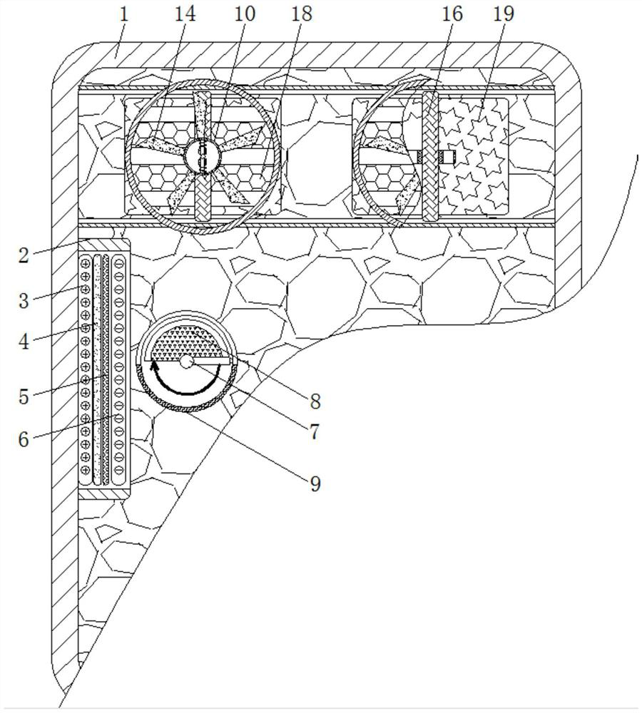
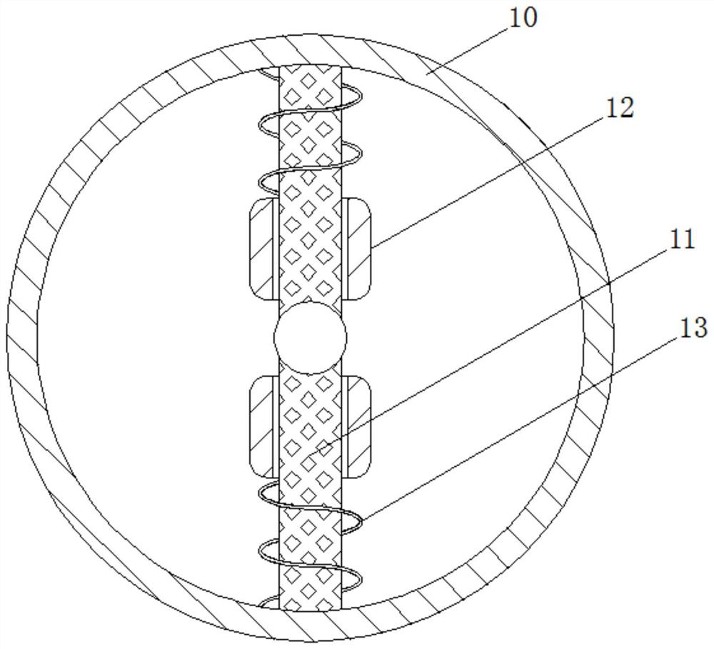
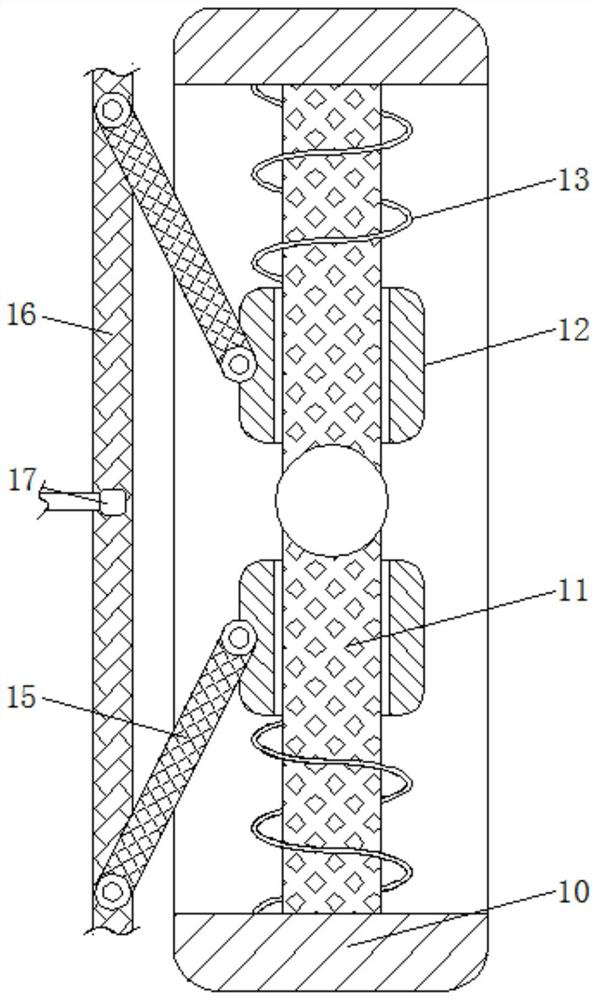
[0023] see Figure 1-4 , a moisture-proof dehumidification device for electrical cabinets, comprising an electrical box 1, a humidity sensing device 2 is fixedly connected to the inside of the electrical box 1, a positive plate 3 is fixedly connected to the inside of the humidity sensing device 2, and the right side of the positive plate 3 is arranged There is a medium plate 4, the right side of the medium plate 4 is provided with a moisture-sensing film 5, th...


PUM


Abstract

The invention relates to the technical field of electric appliance accessories, and discloses a moisture-proof dehumidification device for an electric appliance cabinet. The device comprises an electric box, a humidity sensing device is fixedly connected to the interior of the electric box, a positive plate is fixedly connected to the interior of the humidity sensing device, a dielectric plate is arranged on the right side of the positive plate, and a humidity sensing film is arranged on the right side of the dielectric plate. A negative plate is arranged on the right side of the humidity sensing film, a rotating head is arranged on the right side of the humidity sensing device, and a coil spring is arranged on the upper side of the rotating head. According to the damp-proof dehumidification device for the electric appliance cabinet, through cooperative use of an electric box, the humidity sensing device, the positive plate, the dielectric plate, the humidity sensing film, the negative plate, the rotating head, a coil spring, a resistor, a rotating shaft, a sliding rod, a centrifugal block, a spring, a ventilation fan, a connecting rod, a pushing rod, a sliding rail, a heater and a ventilation door, the humidity in the electric box can be automatically detected; and the dehumidification device is automatically started to prevent electronic components in the electrical box from being affected with damp.

Description

technical field [0001] The invention relates to the technical field of electrical accessories, in particular to a moisture-proof and dehumidifying device for an electrical cabinet. Background technique [0002] Electrical boxes are now widely used in various industries, but there is usually no dehumidification and drying device in the existing electrical boxes, and if the humidity in the electrical box is too high, it may cause the electronic components inside to be damp and affect its normal operation. Work runs, and even a short circuit catches fire, etc., resulting in losses. Contents of the invention [0003] (1) Solved technical problems [0004] Aiming at the deficiencies of the prior art, the present invention provides a moisture-proof dehumidification device for electrical cabinets, which has the advantages of being able to automatically detect the humidity inside the electrical box, and automatically turn on the dehumidification device to prevent the electronic c...

Claims


Application Information

Patent Timeline
Patent Type & Authority Applications(China)
IPC IPC(8): H05K5/02H05K7/14H05K7/20B01D53/26
CPCB01D53/26H05K5/0217H05K7/14H05K7/20136
Inventor 孙梓涵
Owner 扬州唯希信息技术有限公司
Learn More