Eureka AIR delivers breakthrough ideas for toughest innovation challenges, trusted by R&D personnel around the world.

Cup body inner wall sweeper

A cleaning machine and cup body technology, applied in the field of cup inner wall cleaning machines, can solve the problems of easy deformation, easy heating of the nozzle, low labor efficiency, etc.

Inactive Publication Date: 2021-04-27
马行坤
View PDF0 Cites 0 Cited by
  • Summary
  • Abstract
  • Description
  • Claims
  • Application Information

AI Technical Summary

Problems solved by technology

In the process of forming the glass tube by the above-mentioned integral molding method, since the nozzle part is easily heated and easily deformed, it needs a later shaping process to realize it. The traditional method is to use manual shaping, so the labor efficiency is low.
[0003] In addition, when many cups or tubes need to be reused, the inner wall needs to be completely cleaned and cleaned. At present, there is no automatic equipment suitable for cleaning the inner wall of the cup and the mouth of the cup.

Method used

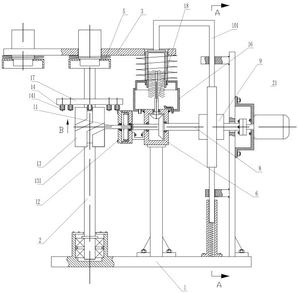
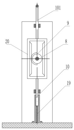
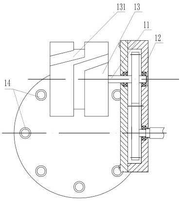

Image

  • Cup body inner wall sweeper
  • Cup body inner wall sweeper
  • Cup body inner wall sweeper

Examples


Embodiment Construction

[0021] refer to figure 1 , figure 2 and image 3 , the present invention provides a cup inner wall cleaning machine, which includes a frame 1, the structure of the frame 1 can refer to figure 1 The structure shown in , of course, can also be designed into other shapes according to needs, the purpose of which is to support and fix the various components on the rack, and is not limited to the structure shown in the figure. The frame 1 is rotatably connected with a vertically arranged active power shaft 2, and the top of the main power shaft is equipped with a rotating bearing plate 3 that rotates with it. Sliding clamping cylinder 5, in this embodiment, the clamping cylinder 5 includes a clamping cylinder connected to the rotating carrier plate 4 through a clamping spring, the clamping cylinder is provided with a cup body to be processed The sleeve clamped by the outer wall, that is, as shown in the figure, the sleeve is located on the rotating bearing plate 3 and protrudes ...


PUM


Abstract

The invention discloses a cup body inner wall cleaning machine which comprises a machine frame, a main power shaft is rotatably connected to the machine frame, a rotary bearing disc is installed at the top of the main power shaft, clamping cylinders are annularly distributed on the bearing disc, a cleaning and shaping gearbox is installed on the machine frame, and a cleaning and shaping device is installed on the cleaning and shaping gearbox. A driving shaft in power connection with a power machine is installed on the machine frame, a driving half gear is connected to the driving shaft, a driving column is installed on the machine frame, a rack is connected to the driving column, a driving arm is installed on the driving column, a driving head is installed on the driving arm, a rotating driving box is installed on the machine frame, and a shifting driving shaft is in power connection with the rotating driving box. A power cam is connected to the shifting driving shaft, a power disc is installed on the main power shaft, a plurality of driving shifting columns are annularly distributed on the power disc, and a driving cam groove for driving the rotating bearing disc to rotate is formed in the power cam. The cleaning machine has the advantages of being high in cleaning and shaping speed, high in quality and high in labor efficiency.

Description

technical field [0001] The invention relates to a cleaning machine for the inner wall of a cup. Background technique [0002] At present, the production method of single-layer glass mainly includes the integral molding method, that is, firstly, it is made into a glass tube, and the glass tube is used as a raw material, and the two ends of the glass tube are clamped and supported and rotated synchronously, and the middle part of the glass tube is locally heated with a flame. Until the glass is softened, the heating temperature is 820°C -1500°C, using a blade made of a heat-resistant material whose thickness is smaller than the width of the heating area and not compatible with the glass, slowly cut from the middle of the heating area, so that one glass tube gradually forms two A glass at the bottom of the glass; the method has high manufacturing efficiency and low production cost, and in addition, the molding quality of the glass is good. In the process of forming the glass t...

Claims


Application Information

Patent Timeline
Patent Type & Authority Applications(China)
IPC IPC(8): C03C23/00
CPCC03C23/0075
Inventor 马行坤
Owner 马行坤
Why Eureka
Eureka Blog
Learn More