Parallel-flow water circulation condenser

A water circulation and downstream technology, applied in the direction of evaporator/condenser, refrigerator, refrigeration components, etc., can solve the problem of reduction

Active Publication Date: 2021-04-27
SHANGHAI WANXIANG REFRIGERATION EQUIP
View PDF6 Cites 2 Cited by
  • Summary
  • Abstract
  • Description
  • Claims
  • Application Information

AI Technical Summary

Problems solved by technology

[0006] However, in the condensing device disclosed in the above-mentioned patent, when the gas is discharged from the air outlet, a large amount of liquid droplets and water vapor will be taken away, resulting in a continuous reduction in the amount of liquid used for circulating cooling in the shell, requiring frequent external replenishment of liquid

Method used


Image

  • Parallel-flow water circulation condenser
  • Parallel-flow water circulation condenser
  • Parallel-flow water circulation condenser

Examples


Embodiment 1

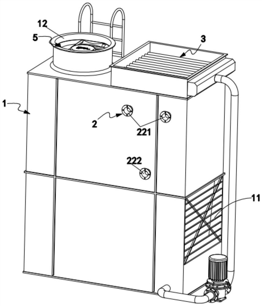
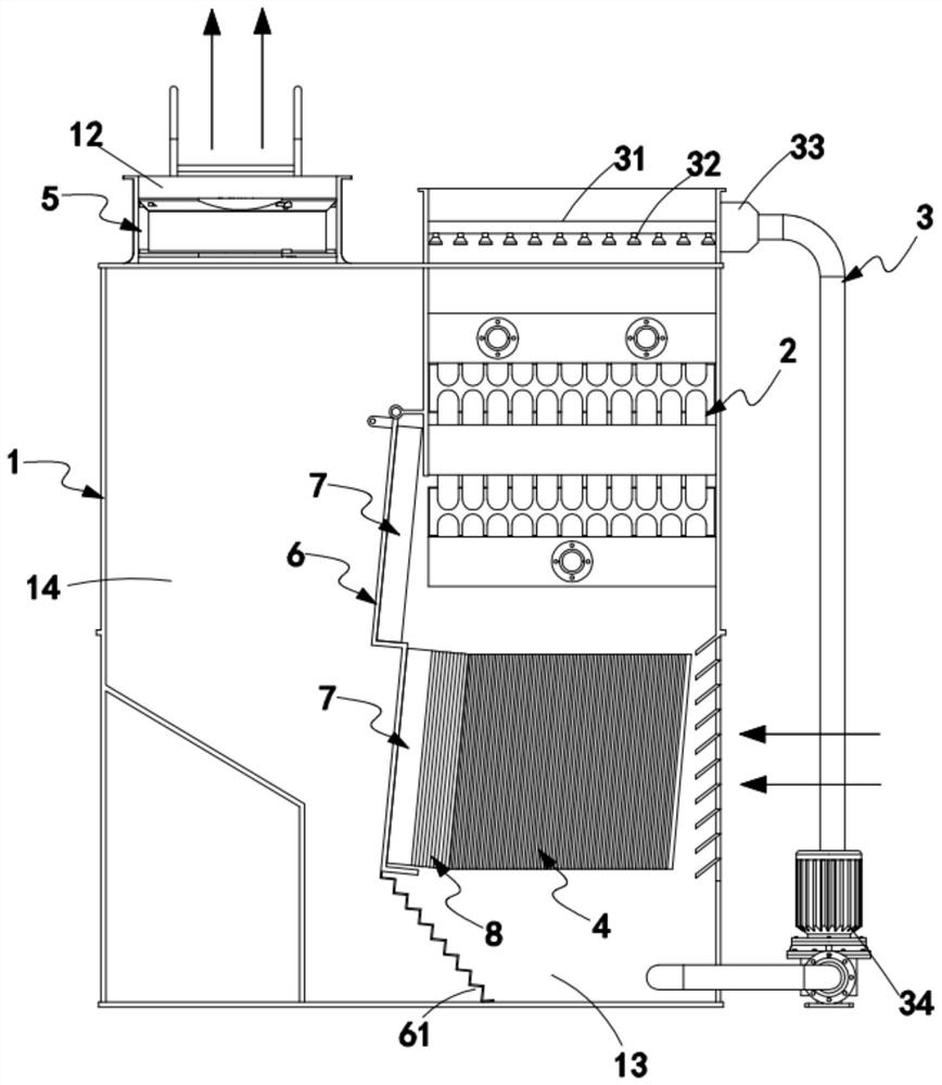
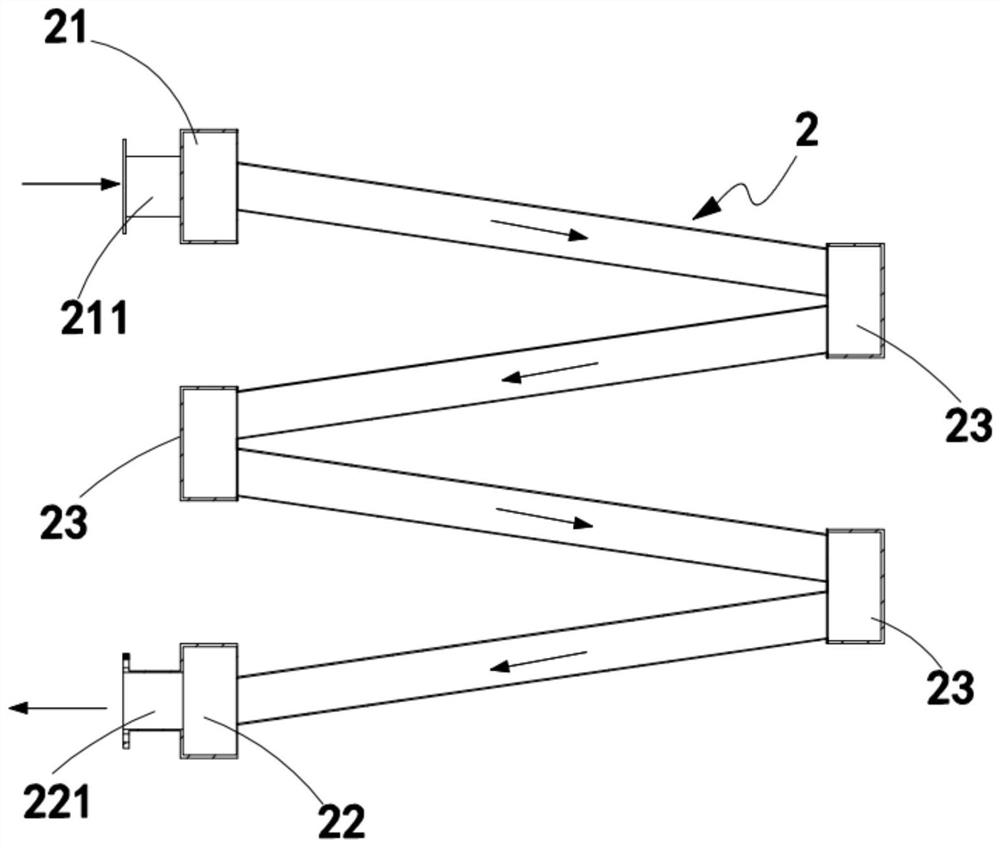
[0059] Such as Figure 1 to Figure 8 As shown, a downstream water circulation condenser includes a housing 1, a cooler 2, a spray mechanism 3, an auxiliary cooler 4 and a fan 5, and the housing 1 is provided with an air inlet 11 and an air outlet 12 respectively. , the cooler 2 is arranged in the housing 1 and the spray mechanism 3 is arranged above, the auxiliary cooler 4 is arranged under the cooler 2, and the fan 5 is arranged at the air outlet 12 :

[0060] A swinging partition 6 is arranged inside the housing 1, and through holes 61 are evenly distributed on the partition 6, and the partition 6 divides the housing 1 into a heat exchange area 13 and an exhaust area 14, so The air inlet 11 is arranged on the heat exchange area 13, the air inlet 11 is arranged facing the auxiliary cooler 4, and the air outlet 12 is arranged on the top of the exhaust area 14;

[0061] A liquid stagnation device 7 is installed on the part of the partition plate 6 facing the cooler 2 and the ...

Embodiment approach

[0070] Such as figure 2 As shown, as a preferred embodiment, the spray mechanism 3 includes:

[0071] Spray pipe 31, a number of said spray pipes 31 are horizontally installed directly above said cooler 2, and said spray pipe 31 is provided with a spray head 32 towards said cooler 2;

[0072] Connecting head 33, described connecting head 33 is positioned at one end of the length direction of described shower pipe 31, and this connecting head 33 communicates with all described shower pipes 31; And

[0073] Circulation pump 34, the circulation pump 34 is installed outside the housing 1, and the circulation pump 34 pumps the spray liquid in the housing 1 cooled by the auxiliary cooler 4 to the connector 33 recycle.

[0074] It should be noted that the circulating pump 34 reintroduces the liquid cooled by the auxiliary refrigerator 4 at the bottom of the housing 1 into the matching spray pipe 31 to achieve the purpose of circulating cooling.

[0075] Such as figure 2 As show...


PUM


Abstract

The invention provides a parallel-flow water circulation condenser. The condenser comprises a shell, a cooler, a spraying mechanism, an auxiliary cooler and a fan, wherein an air inlet and an air outlet are formed in the shell, the cooler is arranged in the shell, the spraying mechanism is arranged above the cooler, the auxiliary cooler is arranged below the cooler, the fan is arranged at the air outlet, liquid stagnation devices are installed at the positions, right opposite to the cooler and the auxiliary cooler, of a partition plate, auxiliary liquid stagnation devices are arranged between the liquid stagnation devices and the auxiliary cooler, liquid carried by gas passing through the auxiliary cooler is retained in the shell through the auxiliary liquid stagnation devices, the liquid is retained in the shell as much as possible, balance of the liquid in the shell is maintained, therefore, a material spraying assembly can continuously and circularly spray and cool, and the technical problem of continuous loss of liquid of an existing condensing device is solved.

Description

technical field [0001] The invention relates to the technical field of mechanical structure of a water circulation condenser, in particular to a downstream water circulation condenser. Background technique [0002] The evaporative condenser is a highly efficient heat exchange device. It is a shell-and-tube condenser, cooling tower, circulating water pump, pool and connecting water pipes. It has the advantages of small footprint, convenient installation, low noise, water saving, power saving, low operating cost, no pollution to the environment, and long service life. And many advantages such as easy maintenance, is an environmentally friendly energy-saving product. [0003] At present, the product has been widely used in beer, pharmaceutical and chemical industry, synthetic ammonia, methanol, coal, construction, aquatic food and other industries. [0004] The condenser of this structure uses water and air as the cooling medium, and is divided into left and right chambers. T...

Claims


Application Information

Patent Timeline
Patent Type & Authority Applications(China)
IPC IPC(8): F25B39/04
CPCF25B39/04F25B2339/041
Inventor 叶军杨程建徐斌马云露宋浩
Owner SHANGHAI WANXIANG REFRIGERATION EQUIP
Why Eureka
Try Eureka